
User's Manual

Teledyne API Model 401 O
3
Photometric Calibrator Instruction Manual, 01124, Rev. J2
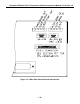
10. Turn on the M401 by switching the switch on the lower right corner of the front panel (See
Figure 2-1). The front panel display should light with a sequence of messages,-API - M401 -
software version number, then a normal display as shown in Figure 2-2.
11. Allow about 60 minutes for the temperatures to come up to their respective setpoints then
press the leftmost button on the front keyboard to scroll through the TEST values. Compare
these values to those noted during the final factory checkout listed in Table 1-1. The values
observed should closely match the Table 1-1 values.
NOTE
Words in all caps are messages on the analyzer front panel.
12. Select the range the analyzer will be calibrated on.
a. From the MAIN menu press SETUP to enter the SETUP menu. (See Figure 2-2 for
appearance of front panel.)
b. Press MISC.
c. Press D/A.
d. Enter the PASSWORD (818).
e. Press RNGE (RANGE).
f. Enter the derived full scale range for analog outputs and press ENTR. (Example: if full
scale range is 500 ppb, then press corresponding digit's button until desired range is
selected and press ENTR.)
g. Press EXIT 3 times to return to the MAIN menu.
13. O
3
generator flow adjustment. The O
3
generator flow is controlled by a precision pressure
regulator and flow restrictor. Increasing upstream pressure of flow restrictor will increase
flowrate and vice versa. In order to increase pressure, adjust knob clockwise as needed while
monitoring the O
3
flow test measurement display. In general, the O
3
generator flow should be
at least 1 L/MIN in addition of total flow demands for the Model 401 (800 cc/min) and
remote analyzers.
NOTE
Adjustment of the O
3
generator flow is to be performed by qualified
maintenance personnel only.
1-9