
User's Manual

Teledyne API Model 401 O
3
Photometric Calibrator Instruction Manual, 01124, Rev. J2
5 DIAGNOSTICS
The Teledyne API ozone analyzer contains two levels of diagnostics: test measurements which
can be viewed at all times (except when in setup) by pressing TEST, and lower level diagnostic
operations which can only be performed by pressing SETUP-DIAG.
5.1 Test Measurements
As stated, test measurements can be viewed at any time except when in setup. To view a
different test measurement, simply press the TEST button. Table 2-3 lists the test measurements
which are available. Viewing these test measurements does not interfere with the operation of
the Model 401 or the ozone reading of the photometer in any way, so they may be viewed freely.
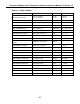
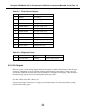
Additionally, the values of most TEST functions can output as an analog voltage at the
instrument's rear panel (see Figure 1-2). The TEST function to be output is selected by pressing
SETUP-MISC-MORE-TCHN. Table 5-1 lists the Test functions available for analog output.
In addition to outputting a value to the analog output channel, these tests activate a new test
measurement which displays the analog voltage reading on the front panel as:
"TEST=XXXXX.X MV".
5.2 Diagnostic Tests
The diagnostic tests are used to help diagnose a problem in the Analyzer and should only be used
by skilled maintenance people. To get into the diagnostic test mode, press SETUP-DIAG. When
the diagnostic mode is entered, a message is sent to the RS-232 channel indicating entry into the
diagnostic mode.
The TEST button is used to scroll through the test measurements until the one of interest is
displayed.
The EXIT button exits the diagnostic mode and turns all the diagnostic tests OFF. This ensures
that a diagnostic test is not accidentally left ON. A message is also sent to the RS-232 channel to
indicate that the diagnostic mode has been exited.
5-1