
User's Manual

Teledyne API Model 401 O
3
Photometric Calibrator Instruction Manual, 01124, Rev. J2
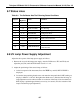
8.2 A/D - D/A Calibration Procedure
Due to the stability of modern electronics, this procedure should not have to be performed more
than once a year or whenever a major sub-assembly is exchanged or whenever analog output
voltage range is changed .
To calibrate the ADC, do the following:
1. Press SETUP-MISC-D/A-CAL.
2. The M401 display will read "DAC #0: 60 mV", where 60 mV
*
is the target voltage which
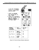
should be coming out the DAC (it should be 60 mV). Put the probe of a voltmeter between
TP3 (AGND) and TP9 (DAC #0) on the top of the V/F card (See Drawing 00514, Appendix
E), then press the up/down buttons on the M400 front panel until the voltmeter displays the
target voltage (60 mV on the 5 V range). Note that the value on the M401 display will not
change. When the voltmeter shows the same value (
± 3 mV) as the M401 display, press
ENTR.
*
The reading will be close to 60 mV if the analyzer is setup for the 5 V range, 120 mV for
the 10 V range, etc. DAC #0 is the recorder output, DAC #1 is the DAS output, and DAC #3
is the test output.
3. The M401 display will now show a new voltage in the same format as above. This voltage
will be 90% of the full scale DAC output range (4500 mV on the 5 V range). As before, press
the up/down buttons on the M401 front panel until the voltmeter displays the same (
± 3 mV)
reading as the M400 display, then press ENTR. The first DAC is now calibrated and will be
used as a voltage reference for calibrating the ADC.
4. The M401 display will now read ZR:60 = 60
± 3 mV, where 60 mV is the voltage being
output from the DAC as input to the ADC, and 60
± 3 mV is the voltage as read from the
ADC. The two values should be the same (60 = 60). If they are not, adjust the zero pot (R27)
on the V/F card (as indicated by ZR on the display) until the two values are the same, then
press ENTR.
5. The M401 display will now read GN:4500=4500
± where 4500 is the voltage being output
from the DAC as input to the ADC, and 4500
± 3 is the voltage as read from the ADC. The
two values should be the same. If they are not, adjust the gain pot (R31) on the V/F card (as
indicated by GN on the display) until the two values are the same (4500 = 4500
± 3 mV),
then press ENTR. The ADC is now calibrated and M401 will automatically calibrate all the
DAC’s. The display will show the percent completion as the analyzer goes through the
procedure.
8-3