
user manual

Teledyne API T703 Calibrator Operation Manual General Troubleshooting & Repair
203
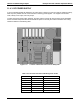
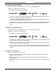
PHOTOMETER PRESSURE SENSOR:
1. Measure the pressure on the inlet side of S1 with an external pressure meter.
2. Measure the voltage across TP4 and TP1.
The expected value for this signal should be:
EXAMPLE: If the measured pressure is 20 Hg-in-A, the expected voltage level between TP4 and
TP1 would be between 2870 mVDC and 3510 mVDC.
EXAMPLE: If the measured pressure is 25 Hg-in-A, the expected voltage level between TP4 and
TP1 would be between 3533 mVDC and 4318 mVDC.
If this voltage is out of range, then either pressure transducer S1 is bad, the board is bad or there is a
pneumatic failure preventing the pressure transducer from sensing the absorption cell pressure
properly.
O
3
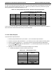
GENERATOR PRESSURE SENSOR
1. Measure the pressure on the inlet side of S2 with an external pressure meter.
2. Measure the voltage across TP5 and TP1.
The expected value for this signal should be:
EXAMPLE: If the measured pressure is 25 psig, the expected voltage level between TP4 and TP1
would be between 3470 mVDC and 4245 mVDC.
EXAMPLE: If the measured pressure is 30 psig, the expected voltage level between TP4 and TP1
would be between 4030 mVDC and 4930 mVDC.
If this voltage is out of range, then either pressure transducer S1 is bad, the board is bad or there is a
pneumatic failure preventing the pressure transducer from sensing the absorption cell pressure
properly.
PHOTOMETER FLOW SENSOR
Measure the voltage across TP3 and TP1.
With proper flow (800 cc
3
/min through the photometer), this should be approximately 4.5V (this
voltage will vary with altitude).
With flow stopped (photometer inlet disconnected or pump turned OFF) the voltage should be
approximately 1V.
If the voltage is incorrect, the flow sensor S3 is bad, the board is bad or there is a leak upstream of
the sensor.
07223B DCN6378