
user manual

General Troubleshooting & Repair Teledyne API T703 Calibrator Operation Manual
204
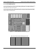
11.4.9. MOTHERBOARD
11.4.9.1. A/D Functions
The simplest method to check the operation of the A-to-D converter on the motherboard is to use the Signal I/O
function under the DIAG menu to check the two A/D reference voltages and input signals that can be easily
measured with a voltmeter.
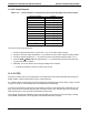
1. Use the Signal I/O function (See Section 11.1.3 and Appendix A) to view the value of REF_4096_MV
and REF
_GND. If both are within 3 mV of nominal (4096 and 0), and are stable, ±0.5 mV then the basic
A/D is functioning properly. If not then the motherboard is bad.
2. Choose a parameter in the Signal I/O function such as PHOTO_LAMP_DRIVE, O3_GEN_TEMP or
PHOTO_FLOW.
Compare these voltages at their origin (see the interconnect drawing and interconnect list in
Appendix D) with the voltage displayed through the signal I/O function.
If the wiring is intact but there is a large difference between the measured and displayed voltage (±10
mV) then the motherboard is bad.
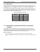
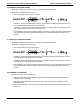
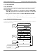
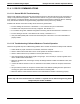
11.4.9.2. Test Channel / Analog Outputs Voltage
To verify that the analog output is working properly, connect a voltmeter to the output in question and perform an
analog output step test as follows:
DIAG AOUT ANALOG OUTPUT
[20%] EXIT
Make sure that
the calibrator
is in standby
mode.
SETUP X.X SECONDARY SETUP MENU
COMM VARS DIAG EXIT
SETUP X.X ENTER PASSWORD
000 ENTREXIT
Toggle to enter
the correct
PASSWORD
DIAG SIGNAL I/O
PREV NEXT ENTR EXIT
DIAG AOUT ANALOG OUTPUT
20% EXIT
Pressing the button under “0%” pause
the test. Brackets will appear around the
value: EXAMPLE: [20%]
Pressing the same button again will
resume the test.
Performs analog
output step test
0% to 100%
STANDBY ACT =STANDBY
<TST TST> GEN STBY SEQ SETUP
SETUP X.X PRIMARY SETUP MENU
O3 SEQ CFG CLK PASS MORE EXIT
07223B DCN6378