TELEDYNE HASTINGS INSTRUCTION MANUAL INSTRUMENTS MODEL 40 POWER SUPPL Y SUPPLY
Manual Print History The print history shown below lists the printing dates of all revisions and addenda created for this manual. The revision level letter increases alphabetically as the manual undergoes subsequent updates. Addenda, which are released between revisions, contain important change information that the user should incorporate immediately into the manual. Addenda are numbered sequentially.
Table of Contents 1.0 GENERAL INFORMATION ....................................................5 1.1 Features .................................................................................................................. 5 1.2 Specifications ........................................................................................................... 5 1.3 Accessories .............................................................................................................. 5 2.
Page 4
SECTION 1 General Information The Hastings Model 40 Power Supply is a combination power supply and digital readout monitor, for up to four Hastings Flow Instruments having the model number prefixes of HFM, ST, or FST and up to 2 of the HFM-D series. The gas conversion factor can be set individually for each channel by front panel mounted potentiometers. This allows meters calibrated for air to be used for other gases without recalibration.
Page 6
SECTION 2 Installation and Operation This section is designed to assist you in getting a new power supply into operation as quickly and easily as possible. Please read the following very thoroughly before attempting to install the instrument. 2.1 Receiving Inspection: Carefully unpack the Hastings Power Supply and any accessories that arrive with it. Inspect it for any obvious signs of damage due to shipment. Immediately advise the carrier if any damage is suspected.
2.3 Output Voltage: The output of the flow instrument is a 0-5.00 VDC signal proportional to the flow rate. The output is sent to the display and is available at terminals at the rear of the Model 40 Power Supply. It is recommended that the load resistance be no less than 2K Ohms. 2.4 Electrical Connection: Ensure that the power switch is turned off. Plug the AC line cord into an appropriately rated receptacle.
2.5 Operation: 2.5.1 Displa y Display If the power supply was purchased with the flow instruments, the power supply will be already set up so that the display reads directly in the units of flow to be monitored. EXAMPLE: A 5 SLPM unit is connected to channel 1. When the CHANNEL SELECTOR switch is turned to channel 1, the display will read 5.00 at 5 SLPM flow rate. A 50 SCCM unit will have the display for its channel read 50.0 at full flow.
2.5.5 Fuse The fuseholder is mounted on the lower right-hand corner of the back panel. To remove the fuse, insert a screwdriver into the slot and turn counterclockwise 1/4 turn. Replace the fuse with a 250 volt 1/4 amp Slo-Blo<190> fuse, 1/4" x 1-1/4". Insert fuse into fuseholder. Place into fuse base and turn clockwise 1/4 turn. Attempting to turn past the stop may damage the fuseholder. 2.5.6 Rear Ter minal Board erminal There is a 14-position terminal board on the rear panel . See Fig. 2.4.
SECTION 3 Calibration and Adjustments This section contains instructions to change the configuration of the power supply from the way it was set up at the factory. 3.1 Range Change: Since the display uses a 3-1/2 digit LCD, the highest number that can be displayed is 1999. If the display is to read directly in the flow units being used, it must be adjusted whenever the highest digit of the maximum flow rate changes, such as, a 20 SLPM flow instrument being changed to 5 SLPM.
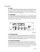
or supply a 5-volt dummy signal to the FLOW-OUT terminals on the back panel. Turn the DISPLAY-ADJUST potentiometer for the channel to be set until the display reads the desired full scale reading. The DISPLAY-ADJUST potentiometers are located on the PC board near the front/center as shown in Fig3.1. Channel 1 is on the right when looking from the front of the Power Supply. 3.1.2 Decimal P oint Point Remove the two screws that hold the aluminum perforated upper cover in place. Slide te cove out.
calculated by comparing ratios of their respective heat capacities. These ratios have been calculated and are tabulated on a chart on page 16 of this manual as THR conversion factors. These factors are used as written only when an instrument calibrated for AIR is being used to measure the flow of a different gas.
3.2.2 Calcula tion of Cor rection F actor or Mass Units Calculation Correction Factor actorss F For Occasionally, a customer will request a flowmeter calibrated in units of mass such as grams/min. or lbs/hour. In this case, another factor must be calculated in to compensate for the different densities of the gases. Calculate the factor as detailed above, then multiply this factor by the ratio of the specific gravity of the new gas to the specific gravity of the gas for which the flowmeter was calibrated.
SECTION 4 Troubleshooting This section contains a troubleshooting guide to help locate and repair failed components. This troubleshooting guide is designed as a general reference only, and will not cover every possible component failure. It is possible for problems with theflow instruments to appear as a failed power supply and vice versa. Therefore, if possible, try to verify the proper operation of the flow instruments on a different power supply.
Check these voltages prior to using the troubleshooting chart. TP-6 is one lead of R27 and should be 2.00 VDC. The flow signals sent by flowmeters on channels 1 - 4 can be accessed by test points on one lead of C7 thru 10 respectively in the left rear of the main PC board. These do not have test point numbers, but their positions are screen printed on the PC board. 4.
SECTION 5 Warranty 5.1 Warranty Repair Policy Hastings Instruments warrants this product for a period of one year from the date of shipment to be free from defects in material and workmanship. This warranty does not apply to defects or failures resulting from unauthorized modification, misuse or mishandling of the product. This warranty does not apply to batteries or other expendable parts, nor to damage caused by leaking batteries or any similar occurrence.