TELEDYNE HASTINGS INSTRUMENTS INSTRUCTION MANUAL IGE 3000 ION GAUGE ISO 9001 C E R T I F I E D
Manual Print History The print history shown below lists the printing dates of all revisions and addenda created for this manual. The revision level letter increases alphabetically as the manual undergoes subsequent updates. Addenda, which are released between revisions, contain important change information that the user should incorporate immediately into the manual. Addenda are numbered sequentially.
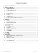
Table of Contents 1. QUICK START INFORMATION.................................................................................................................................... 5 2. GENERAL INFORMATION............................................................................................................................................ 6 2.1. 2.2. 2.3. 2.4. 3. GENERAL INFORMATION ........................................................................................................................
DANGER HIGH VOLTAGE High voltages capable of causing injury or death are present within the IGE 3000 Avoid touching the connector sockets, tube pins and all internal circuitry within the IGE 3000. SERVICE MUST ONLY BE PERFORMED BY QUALIFIED TELEDYNE INSTRUMENTS PERSONNEL. DANGER Do not turn on the IGE 3000 if there is any danger of explosion from explosive or combustible gasses or gas mixtures.
1. Quick Start Information • Apply Power • Apply 24 VDC Power to the “D” connector Pin 3 and 4. • After power is applied the IGE 3000 will go through self test, CPU initialization, and LED test. (The individual LEDs will sequentially illuminate then the IGE 3000 enters the “No Mode” and is operational). • Operate Tube Before operating tube, ensure vacuum is below 1x10⁻² Torr. The IGE 3000 has an automatic shutoff feature that will not allow filament turn on at pressures above 1x10⁻² Torr.
2. General Information 2.1. GENERAL INFORMATION The Teledyne Hastings Instruments IGE-3000 is a small, fully self contained ion gauge electronics module. The mini- Bayard Alpert style ion gauge tube is attached to the electronics module by a 12 pin circular connector. The IGE-3000 is designed for quick, easy installation and will provide the user with long lasting, trouble free, reliable vacuum measurement. 2.2.
2.4.
3. Installation 3.1. INSTALLATION 3.2. Receiving Inspection Your instrument has been manufactured, calibrated and carefully packed so that upon receiving your order it is ready for operation. However, when you unpack, please inspect all items for any obvious signs of damage due to shipment. Immediately advise Teledyne Hastings and the carrier if any damage is suspected.
3.5. “D” Connector Electrical Pin outs The figure below indicates all pin outs. FIGURE 1- IGE-3000 “D” CONNECTOR NOTE: Set Point High, Set Point Low and Remote Start, use Digital ground Pin 8 as signal return path. 3.6. B/A Tube Installation The Bayard/Alpert (B/A) tube may be installed in any orientation. Although the transducer tube is rugged and will perform well in many harsh environments, the tube should be installed in a clean and careful manner.
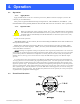
4. Operation 4.1. Operation 4.1.1. Apply Power Apply 24 VDC Power to the “D” connector pin 3 and 4. (Refer to Section 2.5 /Figure 1, for the “D” connector pin out information). After power is applied the IGE-3000 will go through self test, CPU initialization, and LED test. (The individual LED’s will sequentially illuminate then the IGE-3000 enters the “No Mode” and is operational). 4.1.2. Operate Tube Before operating tube, ensure vacuum is below 1x10⁻² Torr.
4.2.1. SELECT SELECT is a push-button. Pressing it will scroll through the different available operating modes. Rapidly “double clicking” SELECT will either turn the selected filament on (if unit is off) or off (if the unit is on) Note: Ensure vacuum is below 1x10⁻² Torr. The IGE-3000 has an automatic shutoff feature that will not allow filament turn on at pressures above 1x10⁻² Torr.
4.3.3. DGas Mode: CAUTION: BEFORE INITIATING DEGAS, VACUUM MUST BE AT OR BELOW 1x10⁻⁷ EXCESSIVE DEGASSING AT ANY TIME CAN DISTORT THE GAUGE ELECTRODES AND CAN RESULT IN A MISLEADING TRANSIENT DECREASE IN PRESSURE INDICATION Degas mode is used to “Degas” or clean the inside areas of the BA tube of impurities. Degassing the tube can improve readings and accuracy. Degassing is not effective at pressures above 1x 10⁻⁷.
The IGE-3000’s filament may be controlled remotely via the D power supply connector by wiring relay contacts or a transistor switch across pins 8 and 9, (refer to section 2.5 /Figure 1 and Figure 3 below). Pin 8 is digital ground and pin 9 is the filament control line. The IGE filament will turn on when pin 9 is pulled low or grounded. This may be accomplished either by relay contacts or by utilizing a transistor switch.
5. Theory of Operation The functional parts of a typical ionization gauge tube are the filament (cathode), the grid (anode), and the ion collector (refer to Figure 4 below). The IGE-3000 control circuit maintains the grid voltage is maintained at 30 VDC, the grid voltage is maintained at 180 VDC, and the collector is 0 VDC relative to ground. A current passed through the filament causes it to heat up sufficiently enough to cause electron emission.
6. Set Up Guide 6.1. ADVANCE SETUP GUIDE The IGE-3000 has several setup and control commands which can be accessed by using the ADJUST rotary encoder and SELECT push-button while viewing the display. Note that most of the commands, which are described below, can be accessed using equivalent RS232/485 Commands. The advanced setup is accessed from NO MODE, the default run mode. Each click of the ADJUST rotary encoder in the clockwise direction will advance the display through each command.
6.4. Data Bits/Parity Bits/Stop Bits P8n1 The first character, “8” corresponds to the number of data bits. (e.g. 7 or 8). Second character, “n” corresponds to the parity bit. (i.e. n- no parity, E- even parity, o- odd parity, 0space, 1- mark) The last character, “1” corresponds to the number of stop bits. (e.g. 1 or 2) 8n1, 8n2, 7n2, 7E1, 7E2, 7o1, 7o2, 701, 702, 711,712 Note: There is no equivalent RS232/485 command. 6.5. Turnaround Delay dt06 dt00, dt01, ...
7. RS 232/RS 485 7.1. RS232/RS485 The IGE-3000 is designed to communicate with external devices by either RS232 or RS485 via the two RJ-11 connectors. Refer to section 3.2 Figure 2 for connector locations. RS232 via the left connector on and the RS485 is via either connector. Software capable of communicating with the IGE-3000 is available upon request. Refer to Figure 7 below for pin out and wiring information. 7.1.1. Wiring for IGE-3000 RS232/485 7.1.2.
8. Device Status 8.1. ION GAUGE DEVICE STATUS: 4-DIGIT OCTAL WORD When requested to transmit its status the IGE-3000 responds with a 4-digit octal word. FIGURE 7 -1 – DIGIT OCTAL WORD • • • bit 11: Serial Receiver Overload bit 10: Main Board EEPROM Error. bit 9: Communication Syntax Error. • • • bit 7 Emission Setting. bit 8 Emission Setting. bit 6: Filament Selection. (0=filament 1, 1=filament 2) FIGURE 8- BITS 7 & 8 EMISSION CODE 8.2. BITS 7 & 8 BIT 8 BIT 7 NO EMISSIONS 0.01 Ma 0.
• When entering more than one command in the same data string, they must be separated by a comma. • All command strings must be followed by the terminator character (carriage return , also known as ENTER). • When a lower case character is present in an example it represents an option.
9. WARRANTY 9.1. Warranty Repair Policy Hastings Instruments warrants this product for a period of one year from the date of shipment to be free from defects in material and workmanship. This warranty does not apply to defects or failures resulting from unauthorized modification, misuse or mishandling of the product. This warranty does not apply to batteries or other expendable parts, or to damage caused by leaking batteries or any similar occurrence.
10.