OPERATING INSTRUCTIONS FOR Model 7500ZA NDIR Infrared Gas Analyzer P/N M7500ZA 4/09/14 DANGER Toxic gases and or flammable liquids may be present in this monitoring system. Personal protective equipment may be required when servicing this instrument. Hazardous voltages exist on certain components internally which may persist for a time even after the power is turned off and disconnected. Only authorized personnel should conduct maintenance and/or servicing.
Model 7500ZA Copyright © 2014 Teledyne Analytical Instruments All Rights Reserved. No part of this manual may be reproduced, transmitted, transcribed, stored in a retrieval system, or translated into any other language or computer language in whole or in part, in any form or by any means, whether it be electronic, mechanical, magnetic, optical, manual, or otherwise, without the prior written consent of Teledyne Analytical Instruments, 16830 Chestnut Street, City of Industry, CA 91748.
NDIR Gas Analyzer Specific Model Information It is not recommended that this instrument be used for analysis on any other gas or gas mixture than that specified at the time of purchase. The analyzer is set up and calibrated at the factory for a specific application using a known gas mixture that is representative of the customers’ process. Using this instrument to analyze any other gas mixture may result in interference and possible measurement error.
Model 7500ZA Safety Messages Your safety and the safety of others is very important. We have provided many important safety messages in this manual. Please read these messages carefully. A safety message alerts you to potential hazards that could hurt you or others. Each safety message is associated with a safety alert symbol. These symbols are found in the manual and inside the instrument.
NDIR Gas Analyzer IF YOU USE THE ANALYZER IN A MANNER OTHER THAN THAT FOR WHICH IT WAS INTENDED, UNPREDICTABLE BEHAVIOR COULD RESULT POSSIBLY ACCOMPANIED WITH HAZARDOUS CONSEQUENCES. This manual provides information designed to guide you through the installation, calibration operation and maintenance of your new analyzer. Please read this manual and keep it available. Occasionally, some instruments are customized for a particular application or features and/or options added per customer requests.
Model 7500ZA Additional Caution on Safety To operate the analyzer properly, be sure to read “Caution on Safety” carefully. The descriptions listed here provide important information on safety. Be sure to observe them at all times. These safety precautions are classified into 3 levels: “DANGER,” “CAUTION” and “PROHIBITION”. ” DANGER Improper handling may cause dangerous situations that may result in death or serious injury.
NDIR Gas Analyzer The gas analyzer is heavy. To transport the analyzer, please use a hand cart or equivalent. Avoid carrying analyzer by hand as much as possible. Doing so may cause injury. Take care not to let cable chips and other foreign objects enter the unit during installation work. Otherwise, fire, failure, or malfunction may result. Caution on piping DANGER Be sure to observe the following precautions while installing piping. Improper piping may result in gas leakage.
Model 7500ZA the ratings of the instrument. Otherwise, electric shock or fire may result. Be sure to connect a power supply of correct rating. Otherwise, fire may result. Caution on use Be sure to read the instruction manual for reference gases before handling reference gases such as calibration gas to use them properly. DANGER Leaving the analyzer unused for a long time or restarting it after long-term suspension requires procedures different from normal operation or suspension procedures.
NDIR Gas Analyzer CAUTION Be sure to observe the following to perform work safely, avoiding electric shock or injury. Remove the watch and other metallic objects before work. Do not touch the instrument with wet hands. If the fuse is blown, eliminate the cause and replace it with the one of the same capacity and type. Otherwise, electric shock or accidents may result. Do not use replacement parts other than those specified by the manufacturer.
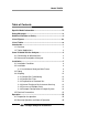
Model 7500ZA Table of Contents Specific Model Information ......................................................... iii Safety Messages .......................................................................... iv Additional Caution on Safety ...................................................... vi List of Figures ............................................................................ xiv List of Tables ............................................................................... xv Introduction ..
NDIR Gas Analyzer Display And Operation Panels ................................................... 27 5.1 Front Panel Description 27 5.2 Overview of Display and Operation Panels 29 5.3 Outline of Display Screen 30 5.4 Basic Operation 34 Settings and Calibration ............................................................. 35 6.1 Range Switch 35 6.1.1 Setting the Range Switch Mode 35 6.1.2 Manual Range Mode 36 6.1.3 Range Identification Contacts 36 6.2 Calibration Setting 37 6.2.
Model 7500ZA 6.7.2 Error Log screen 6.7.3 Calibration Log screen 6.7.4 Output Adjustment Screen 6.7.5 Other Parameter 6.8 Calibration 6.8.1 Zero Calibration 6.8.2 Span Calibration 68 69 70 71 73 73 74 7. Maintenance ............................................................................ 75 7.1 Daily Check 75 7.2 Daily Check And Maintenance Procedures 76 7.3 Long Term Maintenance 76 7.4 Cleaning the Sample Cell 78 7.4.1 Sample Cell Disassembly 78 7.4.1.1 Pipe Cell Removal (See Fig. 7-1) 79 7.4.1.
NDIR Gas Analyzer 9.3 Code Symbols 9.
Model 7500ZA List of Figures Figure 2-1A: Model 7500ZA Front Panel ......................................... 4 Figure 2-1B: Model 7500ZA Rear Panel ......................................... 5 Figure 7-1: Measuring Unit Configuration (Pipe Cell) .................... 79 Figure 7-2: Measuring Unit Configuration (Block Cell) ..................
NDIR Gas Analyzer List of Tables Table 7.1 Maintenance and Check Table ...................................... 76 Table 8-1: Error Messages ............................................................
Model 7500ZA DANGER COMBUSTIBLE GAS USAGE WARNING This is instrument is approved as an intrinsically safe gas analyzer for use in a category (ia) Group IIC hazardous area. This approval only to the equipment specified installed in accordance with the information contained within this manual. It is the customer's responsibility to ensure safety especially when combustible gases are being analyzed since the potential of gas leaks always exist.
NDIR Gas Analyzer Introduction Introduction 1.1 Overview The Model 7500ZA is designed to measure the concentration of NO, SO2, CO2, CO and CH4 in a sample gas based on the principle that different atomic molecules have a different absorption spectrum in the infrared band and the intensity of absorption is determined by the Lambert-Beer law.
Introduction Model 7500ZA 1.2 Typical Applications The Model 7500ZA is a microprocessor based analyzer with a large LCD display, superior accuracy and a multitude of functions suitable for a variety of applications including: • Combustible gas emissions from boilers or incinerators • Steel gas analysis (blast furnace, steel converter, thermal treatment furnace, sintering (pellet equipment) etc.
NDIR Gas Analyzer Items Included with Analyzer Items included with the Analyzer 2.1 Confirmation of delivered items • The following items are included with you analyzer. Analyzer Fuse (2pcs)) Std: IEC127-2 05x20 mm 250V/2A SB Analog Output Connector (1) 25 pin D-sub male M2.6x4 mm Instruction Manual External Input Connector (1) (External O2/External Zirconia Sensor as specified) Digital Input Connector (3 max with the no. of DIO when digital I/O function is specified).
Items Included with Analyzer Model 7500ZA RS-484 Connector (1) (when provided with communications function) 9 pin D-sub connector male M2.6 x 4 mm Ferrite Core (1) for power cable (When terminal block for power supply is specified) Power Supply Cord (1) (when power input is specified) • 2.2 Name and Description of Analyzer The operator interface is shown in Figure 2-1A and the various connections to the instrument are shown in figure 2-1B.
NDIR Gas Analyzer Operation Figure 2-1B: Model 7500ZA Rear Panel Teledyne Analytical Instruments 5
Items Included with Analyzer Model 7500ZA [Blank page] Teledyne Analytical Instruments 6
NDIR Gas Analyzer Instalation Installation Installation of the Model 7500ZA NDIR Analyzer includes: Unpacking Mounting Gas connections Electrical connections Calibration DANGER: THIS UNIT IS NOT AN EXPLOSION-PROOF INSTRUMENT. DO NOT USE IT IN A PLACE WITH EXPLOSIVE GASES TO PREVENT EXPLOSION, FIRE OR OTHER SERIOUS ACCIDENTS. CAUTION: ENTRUST THE INSTALLATION, MOVEMENT OR REINSTALLATION TO A SPECIALIST OR THE SUPPLIER.
Installation Model 7500ZA 3.1 Installation Conditions To install the analyzer for optimum performance, select a location that meets the following conditions; 1. This instrument is designed for rack mounting in a standard 19” equipment rack. 2. Indoor use only. 3. Vibration-free. 4. Free of dust and debris and obstruction around the analyzer. 5. AC power: Operating voltage: Rated frequency: Power consumption: 100V to 240 VAC 85V to 264V AC 50/60 Hz 100 VA max. 6.
NDIR Gas Analyzer Instalation • The analyzer weight must be supported at the bottom of the casing. • The analyzer should be installed in a place where ambient temperature is within -5 to 45°C (max. 40°C when two optical units are used, and the power supply is more than 200V AC), and temperature fluctuation during operation is minimum. • Where vibration is unavoidable, protect the analyzer from vibrating.
Installation • Model 7500ZA Entry of dust into the instrument may result in poor performance. Use clean tubing and couplings. • Sample inlet: Attach clean, dry sample gas to the inlet port. Note that the calibration gases ( zero and span) also connect to this port. Input gas flow t should be constant within the range of 0.5 L/min ±0.2 L/min. Sample outlet: Attach tubing for exhausting sample or calibration gases.
NDIR Gas Analyzer Instalation Correspondence between measured components and the optical units is as follows: Measured Components Optical Bench 1 Optical Bench 2 Single measured species: NO, CO2, CO or CH4 Single component None Two measured species: CO2, CO CO2/CO None Two measured species: NO/CO, NO/SO2 NO/CO CO/SO2 Three measured species: NO/ SO2/ CO NO SO2/CO Four measured species: NO/ SO2/ CO NO/CO SO2/CO Teledyne Analytical Instruments 11
Installation Model 7500ZA 3.4 Sampling 3.4.1 Sample Gas Conditioning 1. Dust from the sampling gas should be completely removed using a filter. For the final stage filter, use a filter that removes dust particles down to 0.3µm. 2. Dew point must be lower than the ambient temperature. If vapor is contained in the sample, dew point should be lowered to 2°C using a dehumidifier. 3. If SO3 mist is present in the sample gas, use a mist filter or cooler to remove the SO3 mist.
NDIR Gas Analyzer Without O2 Sensor measurement. Instalation Built-in O2 Sensor External O2 Sensor of 90 to 100% on the measuring range 90 to 100% on the measuring range. 90 to 100% on the measuring range. O2 gas at 1 to 2% — Gas with conc. of 90 to 100% on the measuring range or atmospheric air (21% O2). Span gas for O2 measurement (O2 gas of 95 to 95.5 vol% for reverse range O2 measurement.) 3.4.
Installation Model 7500ZA 3.4.6 Example Configuration of Sample System The following illustrates a typical sample system configuration for five component gas measurement monitoring a combustion exhaust gas from boiler, refuse incinerator, etc. Contact TAI for other system configurations to match your specific application. Name (1) Gas extractor (2) Mist filter (3) Safety drain trap (4) Gas aspirator Description Gas extractor with a heating type stainless steel filter of standard mesh 40µm.
NDIR Gas Analyzer Name (5) Electronic gas cooler (6) Solenoid valve (7) Membrane filter Description Dries the moisture in the sample gas to a dew point of approx. 2°C Used for flowing the calibration gas. PTFE filter used to eliminate fine dust particles. Instalation Name Description measuring the oxygen concentration in sample gas. (Not used when O2 sensor is built-in.) (11) NO2/NO converter Added to NOx Analyzer. A special catalyst material is used for efficient conversion of NO2 to NO 3.
Installation Model 7500ZA (1) Power Supply (standard terminal 1 to 2) Connect the power supply to the power terminal, and connect the ground wire to the grounding terminal (standard terminal 3). Be sure to provide a protective earth connection. Use solderless terminals (for M4) for connection to the terminals (power and earth). See the figure below. For the infrared gas analyzer, install an accessory ferrite core (to the power supply terminal stand side) on the AC power supply wiring line. See below.
NDIR Gas Analyzer Instalation (2) Analog output signal: Analog output connector (A/O) Output signal : 4 to 20 mA DC or 0 to 1 V DC (selected when ordering) Minus lines for the insulation and signal are common from the ground and internal circuit. Allowable load : 4 to 20 mA DC, 550Ω or less 0 to 1 V DC, 100kΩ or more The analog output signals of the instrument are not isolated individually.
Installation Model 7500ZA • Used when the external zirconia O2 sensor or the external O2 sensor is ordered. It is not required or used if the analyzer has a built-in O2 sensor. • Connect the dedicated connector (accessory) to the output of the external zirconia sensor or the external O2 sensor (shipped separately). • When using an external O2 sensor, the input signal should be 0 to 1 VDC with respect to the O2 full scale of the analyzer.
NDIR Gas Analyzer Instalation (4) Contact input/output (DIO): digital input/output connector (DIO 1 to 3) Contact input signal : Voltage is applied from the external 12 to 24 V DC, max 15mA.
Installation Model 7500ZA Teledyne Analytical Instruments 20
NDIR Gas Analyzer • Instalation Isolated output (from each DO and ground) To avoid external interference, the wiring from the analog output signal, O2 sensor input and contact input should be run separately from that of power supply and contact output. Note: Avoid excess noise generated by other nearby equipment, by grounding the analyzer and using properly shielded cables. (5) Communication: RS-485 connector (6) Timing of Contact Output for Calibration 1. Manual calibration: (See “Item 6.
Installation Model 7500ZA 2. Automatic calibration: (See also Section 6.
NDIR Gas Analyzer Instalation [Blank page] Teledyne Analytical Instruments 23
NDIR Gas Analyzer Operation Operation 4.1 Preparation for operation Tube and wiring check • Double-check if tubes of the gas sampling and exhaust ports are correctly connected. • Double-check for proper wiring. 4.2 Warm-up Operation and Normal Operation (1) Operation Procedure 1. Turn ON the power switch on the left side when facing the front panel of the analyzer unit. The measurement screen will appear on the front display panel in a few seconds. 2.
Installation Model 7500ZA [Blank page] Teledyne Analytical Instruments 26
NDIR Gas Analyzer Display and Operation Panels Display And Operation Panels This section describes the display unit and operation panel on the Model 7500ZA as well as the various functions available to the user. 5.1 Front Panel Description Display unit: The measurement screen and the setting items are displayed. Operation panel: The operator interface panel is shown below.
Display and Operation Panels Name Description Model 7500ZA Name Description (1) MODE key Used to switch the mode. (5) ESC key Used to return to the previous screen or cancel the setting midway. (2) SIDE key Used to change the selected item (by moving the cursor) and the numeral digit. (6) ENT key Used for confirmation of selected items or values, and for execution of calibration. (3) UP key Used to change the selected item (by moving the cursor) and to increase the numeral value.
NDIR Gas Analyzer Display and Operation Panels 5.
Display and Operation Panels Model 7500ZA 5.3 Outline of Display Screen (1) Measurement mode screen (appears when the power is turned on) The measurement screen depends on the number of components. The following screen configuration is shown as an example for NO, SO2, CO2, CO and O2 (output: 12 channels). Scroll the UP and DOWN keys to display more than 5 channels. No.
NDIR Gas Analyzer Display and Operation Panels • O2 corrected concentration values: • Ch components in which “cv**” is displayed as “cv CO” in the display are calculated values derived from the following equation. Refer to Section 6.7 Maintenance Mode - Other Parameter. C (21 On ) Cs (21 Os ) where: On: The value of the O2 correction reference value (set by application) Os: Oxygen concentration (Vol%) Cs: Concentration of relevant measured component.
Display and Operation Panels Model 7500ZA (2) Setting/Selection Screen The setting/selection screen is configured as shown below: • In the status display area, the current display item is displayed. • In the message display area, messages associated with operation are displayed. • In the setting item and selection item display area, items or values to be set are displayed, as required. To navigate through the fields, move the cursor to any item using the UP, DOWN and SIDE keys.
NDIR Gas Analyzer Display and Operation Panels (3) Contents of Measured Channel (Ch) The following table gives measurement channels and their contents according to the symbols.
Display and Operation Panels Model 7500ZA 5.4 Basic Operation Measurement mode The measurement mode can display up to 5 channels in a single screen. If 5 channels or more are to be displayed in a single screen, press the UP or DOWN key to scroll the channels one by one. • • • • • User mode displays • Switch Ranges • Calibration Parameters • Alarm Setting • Setting of Auto Calibration • Setting of Auto Zero Calibration • Parameter Setting.
NDIR Gas Analyzer Settings and Calibration Settings and Calibration 6.1 Range Switch 6.1.1 Setting the Range Switch Mode The range switch has three modes: • Manual (MR) • Remote (RR) • Auto Ranging (AR) To set the range switch mode: 1. Press the MODE key while in measurement mode to display the User mode screen. 2. Move the cursor to “Switch Ranges” and press the ENT key. 3. In the “Channel Selection” screen that appears, move the cursor by pressing the UP or DOWN key, and select Ch (component). 4.
Settings and Calibration Model 7500ZA 6.1.2 Manual Range Mode The analysis range for the measured component can be switched manually as follows: 1. (1) Select “MR” as range switch mode, and then press the ENT key. 2. Using the UP/DOWN keys, move the cursor to the desired range selection. The highlighted arrow indicates the currently selectable range. 3. Select it by pressing the ENT key, and analysis will be carried out in that range.
NDIR Gas Analyzer Settings and Calibration 6.2 Calibration Setting This mode is used to set calibration parameters such as span and zero gas concentration, calibration range, and auto calibration settings and range. When The “Calibration Parameters” screen that appears, the data shown at right is illustrated. 6.2.1 Setting the Span Gas Concentration This screen allows you to set the cal gas concentrations for zero and span on each Ch used for calibration. 1.
Settings and Calibration Model 7500ZA 4. Enter calibration gas concentration for zero and span. Use the UP or DOWN key to increment or decrement the displayed value one digit at a time. When the correct number is displayed for that digit, use the SIDE key to move to the next digit and repeat the increment/decrement process with the UP/DOWN keys. 5. After setting, save the entry by pressing the ENT key. The saved value becomes valid with the next calibration event.
NDIR Gas Analyzer Settings and Calibration 1. Select < User mode > → < Calibration parameters > → < Zero calibration >. The Zero Calibration screen will appears as shown. 2. Select the Ch you want to change using the UP or DOWN key and then press the ENT key. The setting content becomes highlighted. 3. Choose whether you want to set the zero values all together or individually by toggling “at once” or “each” with the UP or DOWN key.
Settings and Calibration Model 7500ZA 6.2.3 Setting the Calibration Range This mode is used to set whether the channels use one or both of the calibration ranges. 1. From the Calibration Parameters screen, select Calibration Range. The following screen appears.
NDIR Gas Analyzer Settings and Calibration 2. Select the Ch you want to change by pressing the UP or DOWN key, then press the ENT key. The setting content is highlighted. 3. Toggle between “both” or “current” using the UP or DOWN key. If “both” is selected, zero or span calibration will be performed on both Range 1 and Range 2 on the selected Ch when the calibration is performed.
Settings and Calibration Model 7500ZA 6.2.4 Setting the Component/Range for Auto Calibration In this section you can select the Ch (component) and the range to calibrate on for those components that have the auto ranging (AR) feature enabled. 1. From the User Mode screen select < Calibration parameters > → < Auto calibration component/range >. The “Auto Calibration Component Range” screen appears as shown. 2. Select the Ch you want to change by pressing the or the key. Press the ENT key.
NDIR Gas Analyzer Settings and Calibration The range identification contact is interlocked with the range after the switch. However, if the hold setting is set to “ON,” the contact status before calibration is maintained. 5. Press the SIDE key in the state described in (3), and the highlight is toggled between “enable” and “disable” auto calibration. 6. Select “enable” of “disable” by pressing the UP or DOWN key. 7. Then press the ENT key to save your selection.
Settings and Calibration Model 7500ZA 6.3 Alarm setting 6.3.1 Setting Alarm Parameters The High/Low limit concentration alarms are user adjustable. Five different alarm contact outputs can be used. The setting range is 0100% full scale for each range. To change the alarm setting, set the alarm ON/OFF setting to OFF, and then change the value. 1. Enter the “Alarm Setting” screen from the user mode. The screen shown on the right will display.
NDIR Gas Analyzer Settings and Calibration Alarm Setting Descriptions The alarm contact number can be assigned to any channel. Channels can also have multiple alarms assigned to them. Channel: Channel setting targeted for alarm. H-Limit value: Sets the high limit value (concentration) for alarm. L-Limit value: Sets the low limit value (concentration) for alarm. Kind of Alarm: Select either High limit alarm, Low limit alarm, and High limit or Low limit alarm, HH limit alarm, and LL limit alarm.
Settings and Calibration Model 7500ZA 6.3.2 Hysteresis Setting The alarm hysteresis can be set or changed to prevent chattering of an alarm output about its alarm set point. To set or change the alarm hysteresis: 1. Navigate to the “Alarm Setting” screen and then move the cursor to “Hysteresis” using the UP or DOWN key. Then press ENT to display the screen shown at the right. 2. From this screen enter the hysteresis values by increasing or decreasing the value using the UP or DOWN keys.
NDIR Gas Analyzer Settings and Calibration 6.3.3 Peak Alarm Setting When the peak number of times CO concentration exceeds the upper limit value during measurement reaches the set number, an alarm is provided. The peak alarm and this setting screen appear only when an option is added. 1. Press the MODE key while in the Measurement mode, and the User mode appears. 2. Using the UP or DOWN keys move the cursor to “Setting of Peak Alarm”. Then press ENT. 3.
Settings and Calibration Model 7500ZA Setting Range Alarm value: 10-1000 ppm → 5 ppm step (initial value: 500 ppm) Alarm count: 1- 99 times/hr → (initial value: 5 times) Hysteresis : 0-20 % FS → (initial value: 0% of full scale) [% FS] represents the percentage with the CO range regarded as 100%. Action of Peak Alarm If the CO concentration exceeds the alarm value, counting will begin. If the number of peaks is over the set times per hour, a peak alarm contact output becomes closed (ON).
NDIR Gas Analyzer Settings and Calibration Releasing peak count alarm To release the peak count alarm, set the peak alarm to OFF. Turning on the peak alarm initiates the count at 0. 6.4 Setting Up the Auto Calibration 6.4.1 Auto Calibration Auto calibration is automatically carried out at the time when zero span calibration are set. Before changing the setting of auto calibration, set the auto calibration function to OFF. 1.
Settings and Calibration Model 7500ZA • Cycle : The period between the start time of one calibration and the next (unit: hour/day) • Flow Time : The time required for purging with calibration gas. Time required for replacement of sample gas after the calibration is completed (Set by calibration gas. See the next page.) • ON/OFF: Turns the auto calibration feature ON or OFF. To close the Auto Cal Settings screen or to abort the entry midway, press the ESC key. The previous screen will return.
NDIR Gas Analyzer Settings and Calibration Auto calibration status contact output is closed during auto calibration (NO side), and is open in other cases. Example: Start Time Sun 12:00 Cycle 1 day Flow Time Zero 350 sec 350 sec CH 1 Span CH 2 Span ON/OFF 350 sec CH 3 Span 350 sec CH 4 Span 300 sec CH 5 Span 300 sec Ex.
Settings and Calibration Caution: Model 7500ZA When an auto calibration starts, the measurement screen appears automatically. Any operation other than “Stop Auto Calibration” (see Item 6.4.2) is not permitted during auto calibration. “Stop Auto Calibration” cannot be performed with the key lock to ON. To force a cancel of the auto calibration, set the key lock to OFF and then execute “Stop Auto Calibration”.
NDIR Gas Analyzer Settings and Calibration confirm the execution of auto calibration. Press the ENT key to execute the auto calibration or press the ESC key to cancel. 6.4.2.2 FORCED STOP OF AUTO CALIBRATION This mode is used to stop the auto calibration forcibly. 1. In the “Set Auto Cal” screens point the cursor to “Auto Calibration Stop” using the “UP or DOWN key. Then press ENT. (“Auto Calibration Stop” appears when this screen is selected while auto calibration is performed.) 2.
Settings and Calibration Caution: Model 7500ZA During an auto calibration, all key operations are not permitted other than key lock ON/OFF and “Auto Calibration Stop.” When the key lock is ON, the “Auto Calibration Stop” is locked out as well. To stop “Auto Calibration” forcedly, set the key lock to OFF and then execute “Auto Calibration Stop.
NDIR Gas Analyzer Settings and Calibration 6.5 Setting Auto Zero Calibration 6.5.1 Auto Zero Calibration Zero calibration can be performed automatically using the settings applied in this screen. The channels for which auto calibration is to be performed are determined by the auto calibration settings described in Section 6.2.4. Before changing any of the auto zero calibration settings, set the auto zero calibration to OFF. 1. Enter the “Set Auto Zero Cal” screen from the user mode.
Settings and Calibration • Model 7500ZA Flow Time: The time required for purging with calibration gas. Time required for replacement of sample gas after the calibration is completed (Set by calibration gas. See the next page.) • ON/OFF: Turns the auto calibration feature ON or OFF. To close the Auto Zero Settings screen or to abort the entry midway, press the ESC key. The previous screen will return.
NDIR Gas Analyzer Settings and Calibration Setting the Range Cycle 1 to 99 hours or 1to 40 days (default: 7 days Flow Time 60 to 900 sec (default: 300 sec.) Caution: When an auto zero calibration starts, the measurement screen automatically appears. Any operation other than “Auto Zero Calibration Stop” (see Item 6.5.2) is not permitted during auto zero calibration. “Auto Zero Calibration Stop” cannot be performed with the key lock set to ON.
Settings and Calibration Model 7500ZA 6.5.2.1 EXECUTION OF AUTO ZERO CALIBRATION (ONLY ONCE) 1. In the “Setting of Auto Zero Calibration” screen that appears, point the cursor to “Run” by pressing the UP or DOWN key. Then press ENT. 2. “Run” is highlighted, displaying a message to confirm execution of auto zero calibration. Press the ENT key to execute the calibration, or the ESC key to cancel. 6.5.2.
NDIR Gas Analyzer Settings and Calibration Auto Zero Calibration Screen Example With Ch1 and Ch2 set to enable for auto calibration (see Section 6.2.4): • Zero calibration A message, “Zero cal.” blinks at Ch1 and Ch2. Caution: During auto zero calibration, the only key operations allowed are key lock ON/OFF and “Auto Zero Calibration Stop.” When the key lock is set at ON, even the “Auto Zero Calibration Stop” cannot be used.
Settings and Calibration Model 7500ZA 6.6 Parameter Setting From the Parameter Setting screen you can set or adjust various parameters of the instrument such as time, key lock, etc. Settable items are as follows: Description of setting items • Current Time : Current year, month, date, day of the week, hour, and minute setting. (The display appears in this order.) • Note: The clock backup time is 2 days. If power is turned on after being off for 2 days or longer, the time must be set again.
NDIR Gas Analyzer Settings and Calibration 2. In the “Parameter Setting” screen that appears, perform the value entry or the setting. For the value entry or setting change, use the UP or DOWN key, and the SIDE key to move the cursor to the right. To close the Parameter Setting screen or to abort the entry midway, press the ESC key. The previous screen will return. Setting Range • Hold setting : 0 to 100% FS • Response time : 1 - 60 sec.
Settings and Calibration Model 7500ZA Manual Calibration Auto Calibration Remote Input Screen Display During Holding A “Hold ON” message will blink on the measuring screen during a hold period.
NDIR Gas Analyzer Settings and Calibration But during a manual calibration the screen displays the process of calibration, therefore a “Hold ON” message will not displayed even if the output signal is held, however the screen will display the hold extending time. If the calibration is cancelled after the calibration gas has been supplied, the holding extending time will be performed in either of manual or auto calibration operation.
Settings and Calibration Model 7500ZA 4. On the parameter hold screen that appears, move the cursor to the Ch (component) you want to hold using the UP or DOWN key and then press ENT. 5. A highlighted value indicates that it can be changed. Adjust the highlighted value with the UP or DOWN key and then move the cursor to the right to change the next digit using the SIDE key. 6. After the value is changed, press the ENT key. Note: The setting is expressed as 1/1 full scale range for both respective ranges.
NDIR Gas Analyzer Settings and Calibration Setting Description • The instantaneous measurement value that is displayed cannot be held. (Output only can be held.) Optional modbus communications “Measurement concentration” register values are held. • If set value is selected for hold, instantaneous O2 correction value is calculated and held based on the set value. • Range identification contact output cannot be switched even if the range is switched during the hold.
Settings and Calibration Model 7500ZA Average Value Reset This mode is used to clear all average values, i.e. O2 correction average and O2 average, and restarts averaging. All average values are reset simultaneously. The indication value and output value is 0 ppm, vol% or so at the time of the reset input (based on average period settings). Example: If the average period was set to 1 hour: • Sampling occurs every 30 seconds.
NDIR Gas Analyzer Settings and Calibration On the Parameters screen, when ON is selected for the Backlight Timer function, the time until auto OFF will also display. Press the SIDE key when ON is highlighted and the time setting can be changed. Use the UP or DOWN key to change the time value and then press ENT to save the value. When OFF is selected, the backlight always remains on and does not automatically turn off. Contrast The LCD Contrast is user adjustable.
Settings and Calibration Model 7500ZA 6.7 Maintenance Mode This mode is used to check sensor input values, display of error log or setting of passwords, etc. This is a password protected area. To access the maintenance mode, enter the correct password from the Parameter Setting/To Maintenance screen. 1. Select the Maintenance Mode from the Parameter Setting screen to display the Password Setting screen. 2. Enter the password, and the Maintenance Mode item selection screen will be displayed.
NDIR Gas Analyzer Settings and Calibration 6.7.3 Calibration Log screen Calibration history can be displayed from this screen. Information available includes sensor input value, concentration value, and the date when zero/span calibration was performed for the last 10 calibration events. They are logged according to component. To clear an event, move the cursor to Clear Calibration Log and press the ENT key, and the calibration log is cleared completely.
Settings and Calibration Model 7500ZA 6.7.4 Output Adjustment Screen The Analog Output Adjustment screen allows the user to adjust the 0-1 V and 4-20 mA output signal. Connect a digital multi meter to the specific output terminal requiring adjustment and adjust the value so that 4 mA or 0 V is output at zero concentration and 20mA or 1V is output at full scale or span. 1. Move the cursor using the UP or DOWN key to the output (OUT No. and zero/span) to be adjusted, and then press the ENT key.
NDIR Gas Analyzer Settings and Calibration 6.7.5 Other Parameter The Other Parameter screen hosts 5 user settable functions: • Password Setting • O2 Reference Value • O2 Reference Value Limit • Station Number • Instrument Range Setting To change any of these items: • Press the UP or DOWN key to move the cursor to the item whose setting is to be changed. • The values for password, oxygen correction, limit, and station No. are highlighted. • Press the UP or DOWN key to change the value.
Settings and Calibration Model 7500ZA Station No. This function allows the user to set the station No. for MODBUS communication. It is settable in the range from 00 to 32. Range Setting This function brings up a screen where the user can set the range for which concentration measurements are made. There are two settable ranges for each component each with a minimum and maximum value as requested at the time of purchase. The range to be used can be selected as Range 1 or Range 2. To set the range: 1.
NDIR Gas Analyzer Settings and Calibration 6.8 Calibration 6.8.1 Zero Calibration This function is used for the zero point adjustment. A proper zero gas, suitable for the application, should be used. Refer to section 3.4 “Sampling”. 1. From the Measurement screen, press the ZERO key to display the Manual Zero Calibration screen. 2. Select the Ch (component) to be calibrated using the UP or DOWN key and then press the ENT key, and zero gas will be admitted to the analyzer.
Settings and Calibration Model 7500ZA 6.8.2 Span Calibration The Model 7500ZA requires periodic span calibration at or near the full scale value on the range of interest. It requires a prepared standard gas containing a known concentration of the measured species. For span calibration gas on the NOX, SO2, CO2, CO and CH4 channels, TAI recommends using a gas source containing 90-100% of the measured species in a background known to be compatible with the instrument.
NDIR Gas Analyzer Maintenance 7. Maintenance 7.1 Daily Check 1. Zero calibration and span calibration 1. Perform zero calibration. For the calibration procedures, refer to Section 6.8.1 Zero calibration. 2. Following the zero calibration, perform a span calibration. For the calibration procedures, refer to Section 6.8.2 Span calibration. 3. Zero/span calibration should be carried out once a week, or as required. 2. Flow rate check 1. Sample and purge gas flow rates are as follows: Sample gas flow : 0.
Maintenance Model 7500ZA 7.2 Daily Check And Maintenance Procedures Table 7.1 Maintenance and Check Table 7.3 Long Term Maintenance Create a long-term maintenance component procurement plan based on the “Gas analyzer annual inspection plan” indicated below. Gas Analyzer Annual Inspection Plan The recommended replacement period of components varies depending on the installation conditions. 1.
NDIR Gas Analyzer Maintenance Installation Conditions 1. Ambient temperature: -5°C to +40°C 2. Humidity: 90%RH or less 3. Corrosive gases: None 4. No radiated heat, direct sunlight or rain/wind 5. Dust: No more than local environmental standards permit 6. Vibration: None Sample gas conditions 1. Temperature: +60°C to +800°C 2. Pressure: -3 to +3 kPa 3. Moisture content: 30% or less 4. Dust: 0.1 g/Nm3 or less 5.
Maintenance Model 7500ZA 7.4 Cleaning the Sample Cell Entry of dust or water in the sampling cell contaminates the interior of the cell resulting in drift. If dirty or contaminated, it must be cleaned. Check the sampling device, especially the filter, to prevent the cell from being dust or mist contamination. Caution: Maintenance should be performed only by properly trained and qualified personnel. In addition to the following steps, the user must adhere to any local and regional regulations. 7.4.
NDIR Gas Analyzer Maintenance 7.4.1.1 PIPE CELL REMOVAL (SEE FIG. 7-1) 1. Stop all gas flow. If necessary, purge the pipe cell thoroughly with zero gas. 2. Turn OFF the power switch and disconnect the AC power cord. 3. Remove the cover (six screws). 4. Remove the tube connected to the pipe cell. 5. Loosen and remove the screw (No. 7) holding the cell retainer (No. 11) at both ends of the pipe cell. 6. Remove the cell from the assembly and unscrew the infrared transmission window (No. 14) at both ends. 7.
Maintenance Model 7500ZA 7.4.1.2 BLOCK CELL REMOVAL (SEE FIG. 7-2) For steps 1 to 4, see 7.4.1.1, Pipe Cell Removal. 5. Disconnect and remove detector output cables from detector output circuit board (No.12). Applying identification mark on top of removed cable connector will ensure proper pin assignment later. 6. Unscrew the two screws (No. 10) that hold the detector to the light source unit to remove the detector from the measuring unit. The block cell can be removed together with the detector. 7.
NDIR Gas Analyzer Maintenance Figure 7-2: Measuring Unit Configuration (Block Cell) Teledyne Analytical Instruments 81
Maintenance Model 7500ZA 7.4.1.3 REMOVING THE MEASURING UNIT Refer to Fig. 7-3. For step 1 to 4, see 7.4.1.1, Pipe Cell Removal. 5. Disconnect and remove detector output cables from detector output circuit board (No.12). Applying identification mark on top of removed cable connector will ensure proper pin assignment later. 6. Disconnect wiring to the 2-pin terminals of the IR light source assembly and chopper motor pin connector from the PCB (No. 17). 7. Detach the six screws (No.
NDIR Gas Analyzer Maintenance Figure 7-3: Measuring Unit with 2-Component Block and Pipe Cell Teledyne Analytical Instruments 83
Maintenance Model 7500ZA 7.5 Fuse Replacement 1. Turn “OFF” the main power supply switch to the analyzer. 2. Rotate the fuse holder cap (shown in the figure above) counterclockwise and pull it out. The cap (fuse holder) will contain the fuse. Remove the blown fuse from the holder and replace it with a new one (250VAC/2A, Slo-Blo). 3. Reinstall the fuse holder cap, turn ON the power supply switch. The analyzer will power up normally.
NDIR Gas Analyzer Error Messages 8. Error Messages Table 8-1 lists the error messages that may occur onscreen along with the probable cause for the error. Table 8-1: Error Messages When errors No. 1 to No. 3 and No. 10 occur, analyzing block error contact output closes. When errors No. 4 to No. 9 occur, the calibration error contact output closes.
Error Messages Model 7500ZA 8.1 Troubleshooting When error No. 1 occurs, remove the top cover of the analyzer and check the LED on the light source PCB. If the LED is off, then the error is caused by a light source disconnection. Errors 1-3 and10 indicate an analyzer failure or fault. Contact TAI for assistance. Errors 4-8 indicate that the calibration procedure may be incorrect. Check the following items, and if the error still occurs, contact TAI. 1. Is the calibration gas flowing to the analyzer? 2.
NDIR Gas Analyzer Error Messages • Press the ECS key to delete the error display. • If the ESC key is pressed without removing the cause of an error, the error will be displayed again. • When more than one error occurs, use the SIDE key to move to the next error display. For errors 5 and 7: 8.2 Error Log File When an error occurs, the history is saved in an error log file. The error log file is accessible in the maintenance mode.
Error Messages Model 7500ZA Error Log Screen * Up to 14 errors can be saved in the error history; the oldest error will be deleted one by one every time a new error occurs. * If the power supply is turned OFF, the contents in the error log file will not be lost or damaged. Deleting Error History Press the ENT key on the above screen, and the “Clear Error Log” will be highlighted. Pressing ENT again will clear the error history.
NDIR Gas Analyzer Specifications 9. Specifications 9.1 General Specifications 9.1.1 Standard Specifications Measurement Method: NO, SO2, CO2, CO, CH4: Non-dispersion infrared-ray absorption method Single light source and single beams (single beam system) O2: Fuel cell O2 analyzer (built-in) or paramagnetic O2 analyzer (built-in) or zirconia O2 analyzer (externally installed TYPE: ZFK7) Measured Gas/Range: Min Range Max Range NO 0-200 ppm 0-5000ppm SO2 0-200 ppm 0-10 vol.
Specifications Model 7500ZA O2 External Zirconia 0-5 vol.% 0-25 vol.% Max. 5 components measurement including O2. For reverse range O2 measurement, IR gas measurement is not available (single range O2 only). Measuring range ratio max. 1:10 (except O2) User adjustable ranges between the specified minimum and maximum range. Settable one range or two ranges, low range (Range 1) and high range (Range 2). See Table 1 for possible combinations of components and ranges.
NDIR Gas Analyzer Specifications Allowable load 100KΩ for 0 to 1V DC Refer to Table2 for the channel No. of displayed values and analog output signals. Analog Input Signal: For signal input from externally installed O2 sensor. Signal requirement: (1) Signal from Zirconia O2 sensor (TYPE: ZFK7) (2) 0 to 1V DC from an O2 sensor. Input section is not isolated. This feature is present when an O2 sensor is not built in. * Externally installed O2 sensor must be purchased separately.
Specifications Model 7500ZA Voltage rating: Allowable range: Frequency: Power consumption: Power Supply: 100V to 240V AC 85V to 264V AC 50Hz/60Hz 100VA max. Operating Conditions: Ambient temperature: -5˚C to 45˚C (40˚C max. when 2 optical system at 200V AC power source) Ambient humidity: 90% RH max., non-condensing Storage Conditions: Ambient temperature: -20˚C to 60˚C Ambient humidity: 100% RH max., non-condensing Dimensions (H × W × D): 133 x 483 x 382mm Mass: Approx.
NDIR Gas Analyzer Specifications 9.1.2 Standard Functions Output Signal Hold: Output signals are held unchanged during manual and auto calibrations when HOLD function is ON. The values held are those just before start of calibration mode or setting value. User selectable. Indication of instantaneous values will not be held. Range Switching: Range switch function is available in manual, auto, and remote modes. Only preset switch method is effective. Manual: Allows range to switch by key operation.
Specifications Model 7500ZA 9.1.3 Optional Functions Remote Output Holding: Output signal is held at the last value or preset value by a voltage input to the remote output holding input terminals. Holding is maintained while the voltage is input to the terminals. Indication of instantaneous values are not held. Range Identification Signal: The present measuring range is identified by a contact position.
NDIR Gas Analyzer Specifications circuiting for 1.5 sec or longer. Auto calibration initiates when contacts open. Auto Zero Calibration: Auto zero calibration is carried out periodically at the preset cycle. This cycle is independent from “Auto Calibration” cycle. When zero calibration gas and solenoid valve for opening/closing the calibration gas flow line are installed by the customer, zero calibration will be carried out at the set auto zero calibration timing.
Specifications Model 7500ZA Correction formula: 21 On Cs 21 Os C : Sample gas concentration after O2 correction. C Cs : Measured concentration of sample gas. Os : Measured O2 concentration (Limit setting: 1 to 20% O2) On : Reference O2 concentration (value changeable by setting 0 - 19% O2). Average value after O2 correction and O2 average value calculation: The result of O2 correction or instantaneous O2 value can be output as an average value over the preset period of time.
NDIR Gas Analyzer Specifications Start-stop synchronization ModbusTM protocol Contents : Read/Write parameters Read measurement conc. and instrument status Remark : When connecting via RS-232C interface, an RS-232C ↔ RS485 converter should be used. Atmospheric Pressure Correction: Measure atmospheric pressure and calculate compensation (for use, exhaust port of analyzer must be at atmospheric pressure. After atmospheric pressure correction: Zero point: Not affected. Span point: Change is 0.
Specifications Model 7500ZA 9.1.4 Performance Repeatability: ±0.5% of full scale Linearity: 1% of full scale prior to atmospheric pressure correction (option) Zero drift: ±2% of full scale/week. For auto zero calibration use 500ppm or lower range. Span drift: ±2% of full scale/week Response time (for 90% FS response): 1 to 15 sec electrical response. Within 1030 seconds including purge time of sample gas. Gas replacement time depends on the number of measuring components and measuring range.
NDIR Gas Analyzer Specifications Electromagnetic Compatibility ; EN61010-1 : 2010 Safety requirements for electrical equipment for measurement, control and laboratory use. “Installation Category II” “Pollution Degree 2” EN61326-1 : 2006 Electrical equipment for measurement, control and laboratory use — EMC requirements. 9.1.6 Requirements for Sample Gas Flow rate: 0.5L / min ±0.2L / min Temperature: 0 to 50˚C Pressure: 10 kPa or less (Gas outlet side should be at atmospheric pressure).
Specifications Model 7500ZA Zero gas ; Dry air or atmospheric air (Do not use with CO2 measurement) Span gas ; For other than O2 measurement, each sample gas having concentration 90 to 100% of its measuring range. For O2 measurement, O2 gas of 1 to 2 vol% /remainder N2 gas 2) Reverse range O2 measurement Zero gas; 100vol% O2 Span gas ; For O2 measurement, O2 gas of 95.0%~95.5vol%/ remainder N2 gas *For reverse range O2 measurement, infrared measurable component is not measurable. 9.1.
NDIR Gas Analyzer Specifications 9.2 Table 1 Measurable Component and Range Availability Check Table Procedure for range selection One component analyzer: 1. First determine 1st range, then select 2nd range from the corresponding right column. More than two components analyzer: 1. The 2nd range in the tables for two and more components is maximum available range. 2. Select the 2nd range less than or equal to the “2nd range (max)”.
Specifications Model 7500ZA Teledyne Analytical Instruments 102
NDIR Gas Analyzer Specifications Teledyne Analytical Instruments 103
Specifications Model 7500ZA Teledyne Analytical Instruments 104
NDIR Gas Analyzer Specifications Teledyne Analytical Instruments 105
Specifications Model 7500ZA 9.
NDIR Gas Analyzer Specifications note1) When “D” is specified at 4th digit, Power supply cord is supplied in the scope of supply. Cord specification should be specified at the 20th digit. note2) When only O2 measurement is necessary, “Y” should be specified at 6th digit. note3) When “1” is specified at 7th digit, O2 pt analyzer signal has to be set as 0-1V DC linear corresponding to full scale.
Specifications Model 7500ZA When 4 components measurement is specified and “H” is specified at 22nd digit, 3 points is maximum for alarm output function. note8) When “B” is specified at 24th digit, measuring range should be specified by ppm range code. In this case NO, SO2 and CO measuring range are corresponding range in mg/m3. Please refer to the table shown below for the corresponding range code based on “mg/m3”.
NDIR Gas Analyzer Specifications 9.
Specifications Model 7500ZA [Blank page] Teledyne Analytical Instruments 110