Control Location 1. 2. 3. 4. 5. 6. 7. 8. 9. 10. 11. 12. 13. 14. 15. 16. 17.
Input and Output Terminals VIDEO AND AUDIO INPUT/OUTPUT TERMINALS 1. Video / Audio input for playback for VCR. 2. Video / Audio monitor output . 3. Y Cb Cr input for DVD. *Please keep AC cord unplugged when connecting TV system.
Operation Instructions WARNING: The Main Power Switch (No.6 of the Control Location page ) is the Manually Operated Mechanical Switch (MOMS). It is requested to Manually to turn On and Off the Main power. The Remote control can not cut off main voltage at the TV set. For safety purpose, turn off the Main Switch manually when long time not use the TV or for the long vacation. Press once will turn on the Main supply of the TV set. The Power indicator (No.6 of the Control Location page ) will light up.
Operation Instructions STEP 3 MANUAL TUNING 1.According to above mentioned steps, open the TUNING menu. 2.Move to "MANUAL TUNING"with PROG+/- buttons. 3.Press VOL.+/-buttons , the search is being carried out. When a TV station signal is received , the character stops flicker and the current item moves to program number item. 4. Enter new program number with direct select buttons. Press VOL.+/-to store the program , then the current menu item jumps to "MANUAL TUNING" automatically . 5.Then press VOL.
Operation Instructions TO SELECT COLOR SYSTEM If the color system setting is incorrect, the color of the channel will be abnormal. 1.According to above mentioned steps, open the COLOR SYSTEM menu. 2.Select the correct color system with PROG.+/- buttons ,press VOL+/- to choose . COLOR SYSTEM AUTO PAL SECAM NTSC 3.58 NTSC 4.43 TO SELECT SOUND SYSTEM If the sound system setting is incorrect, the sound and colour of the channel will be abnormal. 1.According to above mentioned steps, open the SOUND SYSTEM menu.
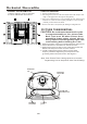
Mechanical Disassemblies CABINET BACK REMOVAL CHASSIS REMOVAL 1. Refer to Figure 1,remove 10 screws. 2. Pull off cabinet back and remove. 1. Remove cabinet back. 2. Discharge the picture tube anode(2nd anode lead) to the dag coating (picture tube grounding lead). 3. Disconnect Degaussing coil socket(KE),Picture tube socket, Deflection yoke connector (KDY), Speaker connectors(KL and KR), and 2nd anode lead. 4. Remove chassis completely by sliding it straight back.
Cabinet Parts List 4 3 10 5 2 9 6 Key No. 1 2 3 4 5 6 7 8 9 10 Part No.