This page is intentionally left blank
Congratulations on your purchase of the TeleMatrix Spectrum PLUSTM Series DC640 Digital Ce ntrex The DC 550 i ncludes advanc ed features that are suitable i n to day’s business e nvironment. The DC550 i s e quipped wi th preprinted fe ature/line ke ys which can be used to customize your telephone features and line appearance. TeleMatrix designed the DC550 to be simple to install and easy to use.
Features .........................................………...................................... 5 Controls …….................................................................................. 6 Part List ……………………………………………………………………………………………...….. 10 Installation ....……......................................................................... 11 Wall Mounting .....…..............................……................................... 14 Programming ..……..............................….................................
• • • Digital Centrex Operation with multi-line functionality • • • • Eleven (11) Access Feature Keys with LED Indicators (Key #M01-M11) • • • • • • • • • • • • • • • • • • LCD Display Management Keys; Up and Down Scrolling SteelTrapTM Memory Technology (No Batteries Required) FreeSpeechTM Talk Feature: Allows Free Toggle between Handset, Headset and Speakerphone TouchLiteTM One Touch Message Retrieval Key (Key #M12) Visual Message Waiting Indication and Visual Ringing Indicator Large, - 2-line x 24-
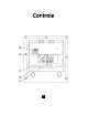
1. Access Feature Keys ….…………..…………... Eleven (11) illuminated pr ogrammable on etouch ke ys used fo r l ine or Ce ntrex fe ature ss. acce 2. To uchliteTM Key...……………………….……….... Message Wai ting L amp (L ED i ndicator) t hat blinks to in dicate a n ew mes sage in th e user’s vo ice m ail b ox (use r m ust b e subscribed to a messaging system). 3. Release Key …………...…………………...……… Used to dis connect the line, place a n ew call or exit the programming mode. 4. Store Key ………...…………………………….….
1. Line Jack …...…………………………………… Modular receptacle for connecting the line cord. 2. Headset Jacks ............................. Convenient RJ port or 2.5mm coaxial port used to connect an optional headset. 3. Handset Jack .............................. Connection for handset coil cord. 4. Power Adapter Receptacle ……..……. For optional coaxial power adapter. 5. Elevation Stand Lock ……………………… Used to “lock” the elevation stand.
Parts Check List The following parts are included with the Spectrum PLUSTM DC550: 1. 2. 3. 4. 5. 6. 7. 8. 9. Bas e Unit H andset 15 foot Modular telephone line cords (2). 10 foot Modular coiled handset cord. 6 inch Modular wall mount line cord. Power Adapter with Pass-Through AC Outlet. Eleven (11) Preprinted Feature Keycaps Fifteen (15) Clear Keycaps Preprinted Feature Key Index Sheet and Blank Labels NOTE: Spectrum PLUSTM Line Cords are 6-Pin 6-Conductor Line cords (6P6C line cord).
Caution • Never install telephone wiring during a lightning storm. • Never i nstall t elephone j acks i n wet l ocations u nless t he j ack i s specifically designed for wet locations. • Never t ouch uni nstalled te lephone wi res or ter minals unl ess the telephone line has been disconnected at the network interface. • Use caution when installing or modifying telephone lines. Power Outlet Required The Sp ectrum PLUSTM Series te lephone requires exter nal po wer f rom a standard 120V outlet (60Hz).
0V AC Outlet Recovery Power Adapter (provided) The 120 VOL T A C OUTLET ADAP TER i s a p roprietary TeleMatrix pr oduct. It p rovides both the telephone lines and the power source in one cable (6P6C line cord) and is designed to recover the use of the AC power outlet. Connector Configuration The 120V O utlet Recovery Power Adapter ha s two (2) mo dular jac ks. One jac k i s labeled “LINE INPUT” and the other jack is labeled “TO PHONE”. These jacks allow for a fully modular installation.
Connecting the Handset Cord A 10-foot modular coil handset cord is provided. ( Be sure that the wall/desk elevation stand has not been attached). To i nstall the co rd, simply plug the short straight end o f the handset cord into the modular jack on the handset. The long straight end of the hands et c ord pl ugs i nto the jac k labeled “Hands et” l ocated on the b ottom of the SpectrumPLUSTM base unit. Place t he l ine co rd i nto t he h andset coil c ord channel lo cated d irectly below the jack.
Wall Mounting the Spectrum PLUSTM Telephone (continued) 2. T he S pectrum PLUSTM h as pr ovisions f or a mounting w edge th at mu st be correctly positioned. T his w edge allow s th e tel ephone t o be viewed at a c orrect angle w hen the p hone is wall mo unted. Remo ve t he w edge f rom t he phone base (figure 2). 3. Secure the line cord, coil cord and any wiring in place prior to installing the wall mount wedge.
Installing Access Feature Keycaps Eleven ( 11) p reprinted a ccess feature keycaps are provided for placement on the access fea ture ke ys. These ke ycaps i dentify t he k eys use. Th ere a re 15 c lear k eycaps pro vided for p rinted labels to be inserted. To i nstall the pre-printed keys, s imply remove t he clear ke ycap b y p ulling i t up with a f ingernail o r s harp o bject. Replace wi th the pre printed keyc aps or pl ace hand written paper i ndex sheets u nder a cl ear k eycap.
Programming Keys The Spectrum PLUS TM DC550 supports the Nortel Meridian Digital Centrex System Environment. The f ollowing page s s how di agrams o n how to p rogram di fferent features of the telephone. Simply follow the instructions on the LCD screen. The keys below are used to program the telephone. PROGRAM KEY (located on base) To enter into the programming mode, press the “PROGRAM” key. EXIT KEY* To exit the program mode, press the “EXIT” key.
Programming Local User Preferences The S pectrum PLUSTM DC550 re quires simple i nitial pr ogramming th at all ows the user to personalize the telephone setup. Quick Program Guide The Spectrum PLUSTM DC550 Quick Programming Guide is a summary list of set up options. Additional detailed instructions are provided in the manual. Programming is initiated by quickly pressing the “PROGRAMMING” key.
Programming Central Office (C.O.) Features Central O ffice ( C.O.) f eatures mu st be a ctivated b y y our loc al te lephone a dministrator or local telephone company Customer Service Representative. Once this is complete, simply label the Active Feature Keys to match the programmed C.O. features. The Spectrum PLUSTM Telephone allows for eleven (11) programmable advanced feature keys to interact w ith th e loc al teleph one Digita l C entrex network.
Programming Users Telephone Features The S pectrum P LUSTM DC550 all ows f or th e u ser t o c ustomize th e te lephone to th e u ser’s preference w hen operatin g. T he f ollowing page s pr ovide in structions on h ow th ese option s are programmed. Setting Up Language PROGRAM Figure THEN PRESS The te lephone LCD ha s the abili ty to display 3 languages: Engli sh, Fr ench, and Spanish. Exit Select Save 1. Press the “PROGRAM” key ( Figure Figure 1).
Programming the Stored Record Memory The Spectrum PLUSTM DC550 allows for up to ten (10) number records to be s tored in the LCD memory for frequently dialed calls. This section describes the programming for the ten (10) LCD Memory locations. These programmed numbers will be saved in LCD Memory. Programming Location Memory Records PROGRAM Figure 1 The telephone has the ability to s tore 10 te lephone number s i nto me mory for future dialing. THEN PRESS Exit 1. Press the “PROGRAM” key (Figure 1).
Programming Volume (Alerter, Speaker, Headset or Handset) 1. Press the “PROGRAM” key (Figure 1 ). P ress t he “UP” or “DOWN” ke y unt il t he d isplay is on t he co rrect “VOLUME?” program, i .e. Ri ng, Spe aker, Headset or Handset (Figure 2). 2. T o a c t i v a t e , p r e s s t h e “SELECT” key (Figure 3). 3. The LCD will display the current settings. Pr ess t he U P/DOWN Key to adjust the volume. 4. Press “SAVE” when the correct volume is displayed. 5.
Programming Default Answer Device (Headset or Speaker) Figure 1 When t he u ser p resses t he l ine key ( i.e. the bottom most Feature Key) the phone will be r equired to pi ck up o n e ither the headset or the speakerphone if the handset is on hook. For example, a receptionist m ight ch oose t o au to an swer calls on a h eadset, w hile s omeone wo rking in a private o ffice mi ght pr efer the speakerphone.
Programming Voice Mail Using the O ne-Touch Messaging f eature, the Voice Mail advanced feature key can be pressed to connect to the Voicemail system on the Nortel Meridian PBX or Central Office switch. Th e swi tch m ust b e p rovisioned for voice mail on the 12th key. The p rogram al lows f or up to 20-di gits. The di gits o f th e P ersonal I dentification Number (P IN) wi ll appe ar on the L CD as they a re e ntered, but will no t appe ar af ter they a re saved.
Programming Voice Mail: Seconds of Wait and PIN Number 1. Once t he V OICE MA IL “VM ONE TOUCH MESSAGING?” is ENABLED, p ress t he “UP” or “DOWN” k ey to ge t the sub m enu. “VM PIN NUMBER:” (Figure 1). 2. Press SELECT (Figure 2). 3. Enter yo ur p ersonal i dentification number (P IN) that wi ll be u sed to retrieve your v oice m ail m essages. In p rogramming mo de, the PIN number wi ll be s hown but o nce saved, the P IN will be shown as asterisks (Figure 3). 4. Press SAVE (Figure 4). 5.
Programming Time and Date 1. Press the “PROGRAM” key (Figure 1). Pr ess the “UP” or “DOWN” ke y until t he di splay shows “TIME AND DATE FORMAT?” (Figure 2). 2. To a ctivate, p ress the “ SELECT” key (Figure 3). 3. There ar e si x different for mat options (Figure 4) plus the option to disable time and date. . 4. When t he de sired f ormat is d isplayed o n the L CD s creen, p ress the “SAVE” key. 5. By pressing “UP”, t he s creen “TIME AND DATE SET?” will appear (Figure 5). 6. Press “SELECT”. 7.
Programming Pre-dial When Pre-dial is enabled, the keypad can be us ed t o di al whil e the te lephone is ON HOOK. After pre-dialing, lift the handset, or press the speaker key, or press the headset key within 12 s econds to pl ace the o utgoing call. 1. Press the “PROGRAM” key (Figure 1 ). Pr ess t he “UP” or “DOWN” k ey until the di splay shows “PREDIAL?” (Figure 2). 2. Press the “SELECT” key ( Figure 3). 3. Enable will be di splayed on the LCD. Press “SAVE” to enable predial.
Programming Call Timer PROGRAM Figure 1 When C all T imer is e nabled, t he LCD wi ll d isplay the e lapsed ti me of an active call when the primary directory number is used. 1. Press the “PROGRAM” key (Figure 1). Pr ess the “UP” or “DOWN” ke y u ntil t he di splay shows “CALL TIMER?” (Figure 2). THEN PRESS Exit 3. Enable will be di splayed o n the LCD. Pr ess “SAVE” to enable Call Timer.
Programming Speakerphone Mode The DC550 includes an option for 2-way Speakerphone or Monitor Mode. When “MONITOR MODE” is enabled, voice transmission automatically stops when the s peakerphone k ey is pr essed. MUT E will activate and the L ED i ndicator will illuminate when the speakerphone i s turned on thr ough the SPEAKER key, or the LINE key, or from an incoming Intercom call.
LCD FEATURES The S pectrum PLU STM LCD d isplay is a 2 -lines x 24-character b acklit d isplay wi th con trast ad justments. The LCD w ill display t he i dentity of the caller a nd t he t ime of t he ca ll. Th e u ser h as t he option to answer the call or allow the call to automatically be forwarded to voice mail. LCD BACKLIGHT FEATURE The S pectrum PLUSTM i s e quipped wi th a bl ue backlit Liquid Crystal Display (LCD) that enhances visibility of the LCD.
Caller Identification (Caller ID) LCD Display Adjustments LCD TILT ANGLE FEATURE The L CD can be ti lted upwar d f or direct vi ewing and e asy re ading. T ilt the L CD to the des ired po sition by lifting up t he bac k o f L CD ho using (Figure 1). (60° maximum upward tilt). LCD CONTRAST FEATURE (16-step) The L CD characters c an be li ghtened or dar kened us ing the c ontrast U P/ DOWN keys (Figure 2).
MEMORY DIAL KEY The M emory D ial key a llows a ccess t o t he Memory for p rogrammed n umbers. Toggle be tween di fferent Me mory Di al numbe rs wh en pre ssing the Me mory Dial key, the “UP” or “DOWN” keys, or the dial pad keys. When the memory location is found, go off hoo k by li fting t he hands et or pr essing the H eadset O n/Off or Speaker keys within 12-seconds to activate that memory dial number. Retrieving and Dialing Stored Memory Records 1. Press the “MEMORY” key (Figure 1).
Headset Feature The Sp ectrum PLUS TM is e quipped wi th a separate por t f or pl ugging in an o ptional headset. T he p ort i s l ocated on the bottom of the ba se un it. T he T eleMatrix FreeSpeechTM Talk Feature is a uni que TeleMatrix feature that allows the user the freedom t o t oggle b etween t he h eadset, handset and speakerphone mo des dur ing a conversation.
Using A Headset The “HEADSET ON/OFF” ke y c ontrols the ac tivation o f the He adset. When usi ng the headset feature, th e hand set rem ains on-hook at all times. Placing/Answering a Call using the Headset On/Off Feature • • • • • To answer an incoming call, press the “HEADSET ON/OFF” key to activate the headset. The LED above the “HEADSET ON/OFF” key will be illuminated when in ON position. Adjust the volume, if necessary. Use the control features of the headset that are available to you.
PREDIALING FEATURE When programmed, the telephone supports a pre-dialing feature for calls made on the Primary Directory Number, or the line corresponding to Feature Key 1 (directly above the Sp eaker k ey). The p re-dial fe ature al lows user s to enter a numb er before l ifting the hands et or us ing the he adset or speakerphone f or an o utgoing call.
SPEAKERPHONE FEATURE The S pectrum PLU STM is e quipped wi th a high qua lity hal f-duplex s peakerphone feature to allow for hands-free operation. To use, simply press the “SPEAKER” key when placing or answering a call. The primary directory line will activate automatically. The LED ab ove the “SPEAKER” key w ill illuminate to i ndicate that the speakerphone is in-use. To d isconnect, simply p ress t “SPEAKER” key or “RLS” key. he Note: Use the VOLUME BAR to adjust the volume of the speaker.
HOLD FEATURE The “HOLD” k ey i s u sed t o p lace a caller o n hold. To use, simply press the “HOLD” key. When t he “HOLD” ke y is a ctive, t he ha ndset can b e l ifted off- hook or returned t o i ts on hook pos ition and the l ine wi ll no t be disconnected. T o return t o t he caller, si mply lift t he hands et or ac tivate the s peaker key and press the blinking line key .
MUTE FEATURE A “MUTE” key is p rovided t o a llow privacy dur ing a ba ckground conversation. Whe n th e “MUTE” key is activated, the mi crophones i n the handset, s peakerphone and/o r he adset a re di sabled. Wh en the “MUTE” key i s a ctivated, the party on the other end o f the l ine will not he ar voice. To de -activate, pr ess t he “MUTE” key again. Note: if the mute feature is auto matically activated each time the s peakerphone is enabled, the ph one may be configured in monitor mode.
Business Feature Keys Advanced feature ke ys a re pr ogrammed b y your T elephone S ystem Ad ministrator or Telephone Service P ersonnel. T hese f eatures a re provided by t he t elephone company i n a Nortel Digital Centrex environment. Only some of the features listed will be available to you because each telephone is customized to a specific business application. Auto Callback Activates the Camp-On feature.
ACD Call Center Feature Keys Agent Agent Avail Agt Status Ans Agent Ans Emergency Call Agent Call Supv Dis Agt Sum Disp Queue EMK Emergency Flex Call Force Call In Calls Interflow LOB MCH Night Serv Not Ready Obs Agent Park Pwr Features Queue Queue Status Supervisor Transfer Allows ACD Supervisor to select the Agent to call when using the Call Agent feature or enables the ACD Supervisor to check the status of all ACD Agent positions when using the Display Agent Feature.
Keep the telephone dry. If it gets wet on the outside, wipe it dry immediately. Liquids might contain minerals that can corrode the electronic circuits. Do not touch the unit if submerged in water. Call for assistance. Use and store the telephone only in normal temperature environments. Temperature e xtremes ca n s horten t he life of electronic devices, damage batteries, and distort or melt plastic parts. Avoid direct sunlight.
When p roblems ar ise during installation o r s ervice t hat c annot be resolved using this or related documents, contact the TeleMatrix Priority Car e D epartment, Monday thro ugh Fr iday, 8:30a. m. - 4:30p. m. MST: www.te Toll Free: 1-800-462-9446 Direct: 719-638-8821 Fax: 719-638-8815 lematrixusa.com Many t imes a p roblem is e ither in stallation o r u ser r elated. P lease contact TeleMatrix PRIOR to sending a telephone to our service center for repair.
STATEMENT OF LIMITED WARRANTY TeleMatrix, Inc.