Installation, Operation & Diagnostics for the MIU202T-S Industrial Grade, Bell 202T-S Standalone Modem Document No. 49-0002-017 Rev.
Telenetics Corporation 26772 Vista Terrace Drive Lake Forest, California 92630 (949)455-4000 Fax (949)455-4010 Document No. 49-0002-017 Rev.
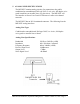
TABLE OF CONTENTS 1. STANDARDS.............................................................................................. 2 2. PRODUCT OVERVIEW ........................................................................... 3 3. GENERAL PRODUCT SPECIFICATIONS ............................................ 4 4. MODEM SPECIFICATIONS ................................................................... 5 5. ANALOG LINE SPECIFICATIONS ........................................................ 7 6.
Meets FCC Rules Part J, Subpart 15, Class A for radiated emissions.
2. PRODUCT OVERVIEW The MIU202T is an industrial grade Bell202T modem for connection to unconditioned and conditioned, voice grade, type 3002 two or four-wire leased lines and metallic lines (eg; pilot wires). It can be powered from a wide range of AC and DC power supplies, it is internally surge protected on both the power and analog lines, and it will operate in temperatures from -40 to +85 deg C. Internally, the MIU202T consists of a baseboard and a communication module.
3. GENERAL PRODUCT SPECIFICATIONS Dimensions: Weight: 5.3 x 4.0 x 1.375 inches 1 lb Voltage Supply: Standard Model: 40 to 270VDC 40 to 270VAC, 50/60Hz 9 to 36VDC LV Model (Suffix “-LV”): Current Requirements: 12VDC 65mA 24VDC 27mA Surge Protection: 125VDC 7.5mA Power Supply: Analog Line: Digital Line: 120VAC 6.5mA 220VAC 5.5mA 8kVrms 3.75kVac ESD ± 10kV Operating Temperature: -40 to +85 deg C Operating Humidity: 0 to 90% (non-condensing.
4. MODEM SPECIFICATIONS Modulation: Modulation Type: Bell202T FSK Synch/Async: Synchronous or Asynchronous Data Rate: 0 – 1200bps Transmit Frequency: Mark: 1200Hz Space: 2200Hz Error Correction: Data Compression: None None Data Modulation Connectivity: Using 16ms Polling Test 99.999% or better at -37dBm 99.
Other Features Receiver Equalization: Compromise Equalization Self Test Diagnostics: None Local Analog Loopback: See Section 13 Local Digital Loopback: See Section 13 Remote Analog Loopback See Section 13 Remote Digital Loopback See Section 13 Anti-Streaming: OFF or 45 Seconds (+ 5 sec) * RTS/CTS delay: 1ms, 12ms, 35ms or 50ms (+5%) * Note: Soft Carrier will effect RTS/CTS delay time (see Dip Switch Settings ~ Section 8) Constant Carrier Switch Selectable ON or OFF Soft Carrier Turn Off 2
5. ANALOG LINE SPECIFICATIONS The MIU202T contains analog circuitry for connection to the public conditioned or unconditioned, Bell type 3002, 2 or 4-wire, full duplex voice grade leased lines or metallic lines (eg; pilot wires). The MIU202T will also interface to Power Line Carrier or Microwave radio voice channel networks. The MIU202T has an RJ-11terminated connector.
6. ANALOG MICROWAVE INTERFACE The MIU202Tis designed to interface to a Microwave radio voice channel network with the following specifications: Phase Jitter (10 to 300Hz)1 degree peak-to-peak, max. Frequency Response: 300 - 3400Hz -3, +0.7 dB 400 - 3000Hz -1, +0.7 dB 600 - 2400Hz + 0.7 dB Frequency Stability: With Synchronization 0.1 Hz Without Synchronization 0.5 Hz / month Level Stability (w/o regulation): + 0.5 dB (6 months) Harmonic Distortion: 1% max, 0.
Crosstalk (unintelligible): Adjacent channel Intra-channel Out of Band Signalling: 28dBrnc0 maximum (24 455B weighted noise at 0 dBmO dBrnc0 typical). 28 dBrnc0, maximum (18 dBrnc0, typical) (1KHz test tone at 0 dBmO) Frequency 3825 Hz Level -20 dBmO Pulse speed (30 to 80% break) 8 to 14 pps Pulse distortion +3 dB, level var. 3% max.
7.
8.
9.
Table 2: RTS/CTS Delay Time 2 4 Switched Constant Wire Wire Carrier Carrier Switch 4 Switch 5 Switch 9 Soft Carrier RTS/CTS Delay Time NO YES NO YES YES NO YES NO YES YES YES YES YES NO NO NO ON ON ON ON ON ON ON ON OFF ON ON OFF 50 ms 50 ms 50 ms 50 ms NO NO YES YES YES YES NO NO YES YES YES YES YES NO NO NO OFF OFF OFF OFF ON ON ON ON OFF ON ON OFF 35 ms 35 ms 35 ms 35 ms NO NO YES YES YES YES NO NO YES YES YES YES YES NO NO NO ON ON ON ON OFF OFF OFF OFF OFF ON ON OFF 12 ms 35
10. MODEM CONFIGURATION The following table provides the Dip Switch settings required for most modem application configurations: 1 4-Wire Point-to-Point 4-Wire Multi-Point Master 4-Wire Multi-Point Slave Rx Term. OFF 4-Wire Multi-Point Slave Rx Term. ON 2-Wire Point-to-Point 2-Wire Multi-Point Master Line Term. ON 2-Wire Multi-Point Slave Line Term. ON 2-Wire Multi-Point Slave Line Term.
11.
12.
13. DIAGNOSTICS The following pages provide hardware techniques for diagnosing communication problems and thereby isolating the problem at the local modem, the remote modem or the interconnecting line. (a) LOCAL ANALOG LOOPBACK (Figure 2) Requires a loop back cable with a built-in circuit for line loss to simulate a typical leased line condition (See Figure 3). Connect the loop back cable to the RJ11 connector on the modem under test.
Set Dip Switch 1 OFF (TxA = -10dBm) and Dip Switch 3 OFF (RxA = -43dBm). CD will be ON. Run a test message at TxD and verify that the same message is received at RxD with no data errors. Test 4: Repeat Test 3 for various RTS/CTS delay times and with soft carrier ON and OFF.
(c) REMOTE DIGITAL LOOPBACK – 4/Wire Network (Figure 5) Configure both the local and remote modems as follows: Switch 1 = ON (TxA = 0dBm) Switch 3 = ON (RxA = -33dBm) Switch 4 = OFF (RTS/CTS = 35ms) Switch 5 = ON (RTS/CTS = 35ms) Switch 6 = ON (Constant Carrier mode). Switch 7 = OFF (4-Wire) Switch 8 = ON (Line Termination = 600 ohms) Switch 9 = ON (Soft Carrier Turn Off = ON) Connect TxD to RxD at the remote modem.
(d) LINE DIAGNOSTICS (i) Typical modem configuration for 4-wire Point-to-Point system… Switch 1 = ON (TxA = 0dBm) Switch 3 = ON (RxA = -33dBm) Switch 4 = OFF (RTS/CTS = 1ms) Switch 5 = OFF (RTS/CTS = 1ms) Switch 6 = ON (Constant Carrier mode).
MIU202T-S Installation, Operation & Diagnostics Edition: March 16, 1999 Page 21
MIU202T-S Installation, Operation & Diagnostics Edition: March 16, 1999 Page 22
MIU202T-S Installation, Operation & Diagnostics Edition: March 16, 1999 Page 23
NOTES: MIU202T-S Installation, Operation & Diagnostics Edition: March 16, 1999 Page 24