¤ DSP9612RM Flash Poll Rack-Mount Modem User’s Guide ARC Electronics 800-926-0226 www.arcelect.com 0049−0519−000 Rev.
Compliances This device complies with Part 15A of the FCC Rules. Operation is subject to the following two conditions: (1) this device may not cause harmful interference, and (2) this device must accept any interference received, including interference that may cause undesired operation. This equipment has been tested and found to comply with the limits for a Class A digital device, pursuant to Part 15A of the FCC Rules.
Contents CHAPTER 1 INTRODUCTION .........................................................5 FEATURES ................................................................................................6 APPLICATIONS .........................................................................................7 ANCILLARY DOCUMENTATION ................................................................7 CHAPTER 2 INSTALLATION ..........................................................9 UNPACKING YOUR HARDWARE .............
Contents NOTES Page iv
Chapter 1 Introduction C ongratulations for purchasing the finest industrial-grade fastpoll rack-mount modem available. The Telenetics DSP9612RM (Flash Poll) modem is a 9600/4800/0-1800 bps rack-mount modem designed for 4-wire, fullduplex or 2-wire, half-duplex operation over a voice-band leased line. The modem is designed utilizing the latest digital-signal processing (DSP) technology to achieve high performance.
Introduction Features Though functionally similar to commercial modems, the DSP9612RM provides the following unique features that make it well suited for utility and industrial applications. c Requires only one rack slot in a Telenetics or a Motorola/UDS RM16M Universal Data Shelf. c Operates over voice-band conditioned or unconditioned leased line and pilot wires. c Operates without human intervention, making it ideal for unmanned locations. c Works within an extended temperature range of -40ºC to +85ºC.
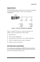
Applications Applications The DSP9612RM modem is designed for point-to-point and multipoint data communications. Figure 1-1 shows a typical multipoint configuration. Figure 1-1. Network of Multipoint Configuration There are a number of factors that can affect the network’s and modem’s operation and performance.
Introduction NOTES Page 8
Chapter 2 Installation T his chapter describes how to install the modem. Unpacking Your Hardware Your package should include: c At least one DSP9612RM modem c This User’s Guide If your package contents are damaged or missing, please contact your place of purchase immediately.
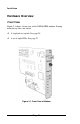
Installation Hardware Overview Front View Figure 2-1 shows a front view of the DSP9612RM modem. Starting from the top, this view shows: c A loopback test switch. See page 28. c A set of eight LEDs. See page 27. Figure 2-1.
Hardware Overview Component View Figure 2-2 shows the component view of the modem. This view shows: c Two configuration switch blocks, designated SW1 and SW2. See page 12. c Jumpers located in various positions on the modem. Do not change or remove the straps from these jumpers. c Edge connectors at the back of the modem, which plug into the backplane of a Telenetics or Motorola/UDS RM 16M Universal Data Shelf. Edge Connectors Configuration Switch Blocks Switch Block SW2 Switch Block SW1 Figure 2-2.
Installation Installation Summary The modem installation involves the following steps: 1. Configuring the modem. See the section below. 2. Connecting to a transmission line. See page 25. 3. Connecting an RS-232 device. See page 26. Configuring the Modem You configure the modem using the two sets of DIP switches on the component side of the modem, near the center. The switches can have one of two functions, depending on how switch SW2-1 is set.
Configuring the Modem Table 2-1.
Installation SW1-1 through SW1-4 − Transmit Level (high- & low-speed modes) Switches SW1-1 through SW1-4 adjust the modem’s transmit level. Table 2-2 shows the transmit levels you can select using these switches. Table 2-2.
Configuring the Modem SW1-5 − Receiver Dynamic Range (high- & low-speed modes) SW1-5 ON = −10 to −43 dBm OFF = +3 to −30 dBm For a low receive signal level, set SW1-5 to ON (−43 dBm ). For short distances or to select a strong receive signal, set SW1-5 to OFF.
Installation SW2-1 − Fast Poll/FSK (high- & low-speed modes) SW2-1 ON = Low-Speed Mode (FSK) OFF = High-Speed Mode (Fast Poll) SW2-1 configures the modem for either low-speed (FSK) mode or high-speed (Fast Poll) mode. As a result, the SW2-1 setting you choose determines the switch definitions for the other switches. c For high-speed mode, the configuration switches follow the definitions in Table 2-1. c For low-speed mode, the configuration switches follow the definitions in Table 2-3.
Configuring the Modem SW2-8 − Carrier Control (high- & low-speed modes) SW2-8 ON = Constant OFF = Switched SW2-8 selects either constant or switched carrier. Constant carrier allows DTEs, such as asynchronous dumb terminals or RTUs, to operate with modems, without the input RTS signal. When constant carrier mode is enabled (SW2-8 set to ON), the modem forces the transmit carrier active and the RTS-CTS delay is minimum (<0.5 ms.).
Installation Low-Speed (FSK) Mode Table 2-3 shows the modem switch settings that can be used when the modem is configured for low-speed (FSK) mode. This mode is enabled when switch SW2-1 is set to ON. Following this table is an explanation of these settings. Table 2-3.
Configuring the Modem SW1-1 through SW1-4 − Transmit Level (high- & low-speed modes) Switches SW1-1 through SW1-4 adjust the modem’s transmit level. Table 2-4 shows the transmit levels you can select using these switches. Table 2-4.
Installation SW1-5 − Receiver Dynamic Range (high- & low-speed modes) SW1-5 ON = −10 to −43 dBm OFF = +3 to −30 dBm For a low receive signal level, set SW1-5 to ON (−43 dBm ). For short distances or to select a strong receive signal, set SW1-5 to OFF. SW1-6 and SW1-7 − RTS-CTS Delay (low-speed mode only) Switches SW1-6 and SW1-7 determine the duration of the RTS-CTS delay. Table 2-5 shows the RTS-CTS delays you can select using these switches. Table 2-5.
Configuring the Modem SW2-1 − Fast Poll/FSK (high- & low-speed modes) SW2-1 ON = Low-Speed Mode (FSK) OFF = High-Speed Mode (Fast Poll) SW2-1 configures the modem for either low-speed (FSK) mode or high-speed (Fast Poll) mode. As a result, the SW2-1 setting you choose determines the switch definitions for the other switches. c For high-speed mode, the configuration switches follow the definitions in Table 2-1. c For low-speed mode, the configuration switches follow the definitions in Table 2-3.
Installation SW2-5 − Soft Carrier (low-speed mode only) SW2-5 ON = Disabled OFF = Enabled SW2-5 controls the soft carrier and is valid for low-speed mode only. Setting this switch to OFF configures the modem to transmit a 900 Hz soft carrier to the remote modem after RTS is turned off. Setting this switch to ON prevents the modem from transmitting a soft carrier after RTS is turned off.
Installing the Modem in the Universal Data Shelf In switched-carrier mode (SW2-8 set to OFF), the RTS/CTS delay is 23 ms. SW 2-9 − RX Termination (high- & low-speed modes) SW2-9 ON = Disable Rx Termination OFF = Enable Rx termination SW2-9 selects whether RX termination is enabled for a modem. If you set this switch OFF, the receiver is terminated with 600 Ω. If you set this switch ON, the receiver is not terminated.
Installation 3. Remove the front panel of the Universal Data Shelf and pick an empty slot. 4. Hold the modem so the front panel LEDs are facing you and the edge connectors are pointing to the backplane of the Universal Data Shelf. 5. Install the modem into the selected slot in the Universal Data Shelf (see Figure 2-3). 6. Push firmly on the modem to seat it properly into the slot and backplane.
Connecting to a Transmission Line Figure 2-4. Modems Installed in the Rack Connecting to a Transmission Line The Universal Data Shelf has different Telco options. Your version may have 16 8-pin modular jack connectors, one for each slot in the Shelf. It may also have an optional 50-pin mass-termination Telco connector. To connect your modem to a leased line using the modular jack connectors, refer to “Modular Jack Connectors,” below.
Installation c The Tx line of the Shelf’s RJ-45 jack must connect to the Rx line of the other modem. For more information, refer to the Telenetics RM16M Installation and Operation Manual for the Universal Data Shelf version you have. Mass Termination Connector As an option, a 50-pin mass-termination connector can be used as the Telco connection for the modem(s). For more information, refer to the Telenetics RM16M Installation and Operation Manual for the Universal Data Shelf version you have.
LEDs LEDs The front panel of the modem provides the LEDs shown in Table 2-7. Table 2-7. Modem LEDs LED Color Description Power Green Power RTS Yellow Request To Send CTS Yellow Clear To Send TxD Yellow Transmit Data RxD Yellow Receive Data DCD Yellow Carrier Detect ALB Red* Analog Loopback DLB Red* Digital Loopback * When the modem is in remote loopback, both the ALB and DLB LEDs go ON.
Installation Loopback Control Switch The front panel of the modem has a push button for initiating the following loopback diagnostic tests: c Local analog loopback started by pressing the button one time. c Local digital loopback started by pressing the button two times. c Remote digital loopback set the local modem’s RTS signal to low. Then press the remote modem’s diagnostics button three times and raise the local modem’s RTS signal to start the test.
Appendix A Troubleshooting I n the event you encounter a problem using your Telenetics modem, refer to the troubleshooting information in this appendix. To troubleshoot the power supply and backplane on the Universal Data Shelf, refer to the Telenetics RM16M Installation and Operation Manual for the Universal Data Shelf version you have. , IMPORTANT If you encounter a problem with your modem, be sure the modem switches are set to the appropriate positions.
Troubleshooting Table A-1. Troubleshooting Suggestions If… Perform These Procedures… The RTS, CTS, and TxD LEDs do not blink. The attached terminal or DTE may not be sending data to the modem. Verify that data is being transmitted. If data is being transmitted, make sure the RS232 cable is sound and securely connected to the modem and terminal or DTE.
Appendix B Specifications General Specifications Data rate: 9600, 4800, or 0-1800 bps asynchronous Data format: 8 or 9 data bits with 1 or more stop bits DTE interface: EIA RS-232 or V.24 compatible Line conditions: TELCO Voice band 4- or 2-wire leased line, conditioned or unconditioned Private metallic circuits up to 9.5 miles (24 AWG) without cable equalizer. Up to 15.
Specifications Receiver dynamic range: 0 to –30 dBm or –10 to –43 dBm Operating temperature: -40°C to +85°C Surge protection: Leased line, up to 15KV Carrier Control: Constant or switched, DIP switch selectable Carrier loss recovery: Train on Data Throughput delay: Less than 10 milliseconds for fast polling.
Back-to-Back Connections to a Second Modem Back-to-Back Connections to a Second Modem Rx Rx Rx Rx Tx Tx Tx Tx Modem 1 Modem 2 RS-232 (RTU) Interface Signal Name Modem Input/Output DB25 Pin Description Earth GND 1 Earth Ground TXD Input 2 Transmit Data RXD Output 3 Receive Data RTS Input 4 Request To Send CTS Output 5 Clear To Send DSR Output 6 Data Set Ready (Modem Ready) SG - 7 Signal Ground DCD Output 8 Data Carrier Detected DTR Input 20 Data Terminal R
Specifications Environmental Specifications Operating temperature: -40 to + 85o C Storage temperature: -40 to +125o C Operating humidity: 5 to 95 %, non-condensing. Isolation: 3750 V RMS Surge protection: Leased line up to 15K VA Compliances The modem is designed to meet the following agency requirements: EMI/RFI: FCC part 15 for Class A computing device Industry Canada.
Appendix C Limited Product Warranty Telenetics warrants that the Product sold will be free from defects in material and workmanship and perform to Telenetics' applicable published specifications for a period of 18 months from the date of delivery to Customer or 12 months from placement into service, whichever occurs first. The liability of Telenetics hereunder shall be limited to replacing or repairing, at its option, any defective Products which are returned F.O.B.
Appendix D RMA Procedure Return Merchandise Authorization (RMA) Procedure Before returning any Telenetics product, an RMA number must be obtained. Before asking for an RMA number, ascertain that the product was purchased from Telenetics. If you bought the product from a Distributor or Systems Integrator, the product should be returned to that vendor. The most convenient method to obtain an RMA number for a product purchased from Telenetics is to send an email to support@telenetics.com.