Installation, Operation and Diagnostics for your Communication Interface Unit MIU(Dial or Lease Line modem with) / 485 (RS485) ~ See MIUXXX for modem Technical Data Edition: June 17, 2003 P/N: 0049-0002-010 rev A
TABLE of CONTENTS 1.PRODUCT OVERVIEW......................................................................... Page 1 2.PRODUCT DESCRIPTION.................................................................... Page 1 3 SERIAL CONNECTOR SPECIFICATIONS ............................................. Page 2 4.POWER SUPPLY SPECIFICATIONS ..................................................... Page 4 5.RS485 SPECIFICATIONS ..................................................................... Page 5 6.
1. PRODUCT OVERVIEW The CIU (MIU\XXX485) is an industrial modem with an RS-232 to RS485 converter module for direct connection to industrial RS485 Interface units. Though similar to commercial modems, the MIUXXX\485 contains special features that make it particularly well suited for industrial applications. (MIUXXX is for any dial or lease line modems such as MIU14.4L) These capabilities include: Environment The CIU has been designed explicitly for use in industrial environments.
3. MIU'S LED, SWITCH & SERIAL CONNECTOR SPECIFICATIONS The CIU/485 communicates with industrial controllers through RS-485 compatible serial signaling. The RS-485 signal levels are used to interconnect with RS-485 compatible embedded controllers. The RS-232E signal levels are used to configure the CIU. The RS232E signal levels are also used to interconnect with RS-232E compatible embedded controllers if required.
3.
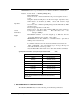
4. POWER SUPPLY SPECIFICATIONS The MIUXXX/485 contains a low quiescent power regulator. TheMIUXXX/485 also has a "low power" standby mode which minimizes overall power requirements when the MIUXXX/485 is used intermittently. 4.1 Power Supply Selection (MIU) The power supply is selected through the use of a 3-pin screw - type terminal connector. Power Connector P3 (MIU) Connector Type: 3 Pin screw- type terminal Regulated Powe r Supply Range: 48.0 to 220 Volts AC/DC.
5. RS485 SPECIFICATIONS MIUXXXX/485 are low-power Transceiver for RS485 and RS422 communication Features: Point to Point or Multidrop/Multipolling Full or Half Duplex Drivers are short - circuit current limited & protected against excessive power dissipation (shutdown will places the drivers in a high - impedance state). When Drivers are disabled (by TXD), drivers will switch to high impedance state.
Operating Temperatures -40 to 85o C Storage Temperature -55 to 100o C Relative Humidity 0 to 95% is non-condensing. Altitude 20,000 ft (operating), 40,000 ft (shipping). Vibration Effect Withstand 10 to 500 Hz at 1 g on any axis per SAMA PMC-31-1 without damage or impairment. ESD susceptibility Field connected circuits meet the requirements of IEC 801-2 for ESD withstand capability up to 10 KV.
MIUXXX\485 Power Connection Power Connector RJ11 Leased Line Port Power In MIU (48 to 220VAC/DC (AC or DC) non-polarized Earth Gnd Power In MIU-LV (9 to 36VDC) Positive Voltage In Power Ground Earth Gnd LED 1 Earth/Digital Ground (Jump pins if req’d) DB9 Data Port LED ONE ♦Blinking = POWER ON Steady = MODEM CONNECTED (CD) CIU Installation, Operation & Diagnostics Edition: June 17, 2003 SHEET TWO
RJ11 Telco Port * Power Connector (* Not on MIU232/485 Converter) B A LED 1 * Earth/Digital Ground (Jump pins if req’d) * RS485 Connection TX+ TX- RX+ RX- RS232 Data Port (DB9 female) for modem configuration only. 3 & 4 always UP. 1 UP, 2 DOWN when using DB9 for modem configuration. 1 DOWN, 2 UP ~ Modem connected to RS485. Do not connect data to DB9 LED 1...
APPENDIX A.
APPENDIX B.
1:AT Command (MIU2400/485) (Dial) configuration is: ATE0Q1&C1&D0S0=1&W0 E0 Echo Command disables (no "AT" response to terminal) Q1 Result Codes disable (no result codes return to terminal ring) S0=1 Auto Answer active (first ring modem will go OFF- Hook and start answer sequence) &C1 Carrier Detect is always True (MIU LED will be ON all the time when Carrier Detect is ON. &D0 DTR is ignored 2: AT Command (MIU2496/485, MIU14.4/485 & MIU28.
&Z3=XX Password to exit security mode &C1 Carrier Detect is always True (MIU LED will be ON all the time when Carrier Detect is ON. &D0 DTR is ignored &K0 No flow control 4: AT Command (MIU9.
SB-1 Closed(ON) DC Terminated SB-2 Closed (ON) Line Termination SB-3 & -4 Open (OFF) 4- wire SA-1 Open (OFF) RTS follows CTS no delay SA-2 Open (OFF) SA-3 Closed (ON) RTS (always ON by MIU internal J7 (1/2) setting) enables TxEN) SA-4 Open (OFF) TxD will not disable RxD MIU S3 (external) SW-1 Closed (ON) MIU is configured for RS485 Module (RS485 RxD (Output) to Modem TxD (input)) SW-2, -3 & -4 Open (OFF) SA2 & SA3 can be configures for TxD enable TxEn signal if there are several master locations in the netw
To test RS485 module set switch SB-3 & -4 Closed (ON) to loopback data to the host modem. This test is for RS485 2- wire and 4- wire configurations. Connect MIUXXXX/485 TXY (+) and TXZ (-) to the embedded controller RS485 DIAGNOSTICS RS485 CONNECTION FAILURE To test RS485 module set switch SB-3 & -4 Closed (ON) to loopback data to the host modem. This test is for RS485 2- wire and 4- wire configurations.