Installation, Operation & Diagnostics for the MIU/PowerPort Series / 2.4 / 9.6 / 14.4 / 28.8 Industrial Grade Dial Modems Book 1 of 2 (See Book 2 for AT Commands) Document No.
Telenetics Corporation 26772 Vista Terrace Drive Lake Forest, California 92630 Telephone (949)455-4000 Fax (949)455-4010 Document No.
TABLE of CONTENTS 1. STANDARDS ....................................................................................Page 2 2. PRODUCT OVERVIEW ...................................................................Page 3 3. GENERAL PRODUCT SPECIFICATIONS .....................................Page 5 4. POWER MODES ...............................................................................Page 6 5. MODEM SPECIFICATIONS ............................................................Page 7 6.
1. STANDARDS All Telenetics dial-up modems are designed to meet the following Standards: USA: FCC Part 15, Class A and Part 68 Canada: DOC Standards CS-01, CS-02 and CS-03 CANADIAN DEPARTMENT OF COMMUNICATION NOTICE NOTICE: The Canadian Department of Communications (DOC) label identifies certified equipment. This certification means that the equipment meets certain telecommunications network protective, operational and safety requirements.
2. PRODUCT OVERVIEW The MIUPowerPortX.X Series are industrial grade dial and leased line modems for connection to the Public Switched Telephone Network.. They can be powered from a wide range of AC and DC power supplies, they are internally surge protected on both the power and analog lines, and they will operate in temperatures from -40 to +85 deg C. Internally, each unit consists of a baseboard and a communication module. The baseboard includes the power supply regulation and surge protection.
Industrial: The MIU PowerPort is packaged in a rugged, compact, non-metallic (ABS) enclosure. Designed for unmanned locations, the MIUs do not include the array of pushbuttons and LEDs normally associated with consumer-type modems to increase reliability and decrease power consumption. Configuration is by dip switches and/or software (“AT”) commands. Standard industrial connectors for data, analog and power interfaces allow reliable interconnection to other industrial components.
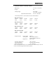
3. GENERAL PRODUCT SPECIFICATIONS Dimensions: Weight: 5.3 x 4.0 x 1.375 inches 1 lb Voltage Supply: : Optional Wall Transformer 8 to 24 VDC 7 to 16 VAC, 50/60 Hz 115 VAC, 50/60 Hz Current Requirements: (See Section 4 for Power Down Modes) MIU PowerPort 2.4: 12VDC 24VDC 65mA 27mA 125VDC 7.5mA 120VAC 6.5mA 220VAC 5.5mA MIU PowerPort 9.6: 12VDC 24VDC 115mA 57mA 125VDC 11mA 120VAC 10mA 220VAC 9mA MIU1 PowerPort 4.4: 12VDC 24VDC 125VDC 160mA 69mA 14mA 120VAC 12mA 220VAC 9mA MIU PowerPort 28.
4. POWER MODES Mode Power On Sleep Description Factory Setting: Full power is always available to the modem. If the modem is on hook for a predetermined period (PE2400 = 5 seconds; PE2496, PE14.4 & PE28.8 = software configured: Set S24 to desired delay in seconds), it will drop to a low current mode). Power Consumption See Section 3 Approx. 6mA The modem will instantly “wake up” to full power by either an incoming ring signal or any transmit data (TxD) signal.
5. MODEM SPECIFICATIONS MIU2.4 V.22bis V.22 Bell212A Bell 103 MIU9.6 V.22bis V.22 Bell212A Bell 103 MIU14.4 V.32bis V.32 V.22bis V.22 Bell212A Bell 103 MIU28.8 V.34 V.32bis V.32 V.22bis V.
6. POWER CONNECTIONS DC Power Jack, 2.0mm – This standard concentric jack is provided to attach an external power source in the range of 7 – 16 VAC or 8 – 24 VDC. The 2.0mm Jack connects through a full wave bridge so either polarity is acceptable from the DC source. The slide switch adjacent to the LED must be to the right side (Toward the 2.0mm Jack). DB – 25, Pin 10 – A DC voltage may be applied at the 25 pin data connector.
7.
8. DIP SWITCH SETTINGS Not Applicable – The dip switches are on the PE Module. Contact factory for non – standard settings. * NOTE: Opening the MIU for any reason voids the factory warranty.
9. LED INDICATOR The MIU has a single LED that will indicate the following conditions... 10. 4 Blinking: POWER ON 4 Steady: MODEM CONNECTED (CARRIER DETECT) AUTO RESET FEATURE The dial-up modem modules inside your MIU include an “Auto Reset” feature: If the modem configuration is lost for any reason, it can be restored by dialing the modem and allowing it to ring 4 to 6 times. The Auto Reset feature is enabled and disabled by a dip switch on the modem module.
12.
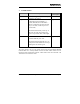
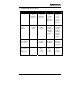
13. MODEM CONFIGURATION Telenetics dial and leased line modems are based upon Rockwell chipsets. These chipsets contain Rockwell’s “AT” command set. A summary of the Rockwell command set for your MIU modem is provided in Book 2. Unless otherwise specified at the time of order, your modem will have left the Telenetics factory in the configuration detailed on the following pages. The Telenetics factory configuration differs from the Rockwell default configuration as follows...
14. FACTORY CONFIGURATION ~ MIU2.
14. FACTORY CONFIGURATION ~ MIU9.
14. FACTORY CONFIGURATION ~ MIU14.
14. FACTORY CONFIGURATION ~ MIU28.
15. DIAGNOSTICS The following pages provide software and hardware techniques for diagnosing communication problems and thereby isolating the problem at either the local modem, the remote modem or the interconnecting line. The following AT&Tn commands form part of the CCITT V.54 protocol and can be used for diagnostic testing. Note: &Tn commands can only be used when the modem is configured for &Q0 (unbuffered/direct asynchronous mode).
&T0 TERMINATE TEST IN PROGRESS If a V.54 loopback test is in progress as a result of executing an &Tn command, then the &T0 command will cause that test to be terminated, provided that the modem is in the command state or a V.54 state that accepts commands from the DTE. See specific &Tn command descriptions for termination actions. &T1 INITIATE LOCAL ANALOG LOOPBACK (See Figure 2) When the AT&T1 command is entered, the modem goes on hook and configures itself for analog loopback.
&T2 NO FUNCTION &T3 PERFORM LOCAL DIGITAL LOOPBACK (See Figure 3) The modem must be in the command state with connection established when this command is issued, otherwise an ERROR result code occurs. The AT&T3 command establishes a loopback of received data, after demodulation, and sends it back to the distant end. The modem is configured for local digital loopback, DSR is turned off (if &S1 is in effect), the test timer is started with the value in S18, and an OK result code is sent to the DTE.
&T5 DENY RDL REQUESTS The modem will not respond to a remote digital loopback request from a distant modem. This will result in an error if the command is given while any V.54 test is active (&T1, &T3, &T6, &T7 or &T8). &T6 INITIATE REMOTE DIGITAL LOOPBACK (See Figure 4) The command is valid only if the modem is in the command state with a connection established. Configure the modem under test with an AT&T4 command so that it will honor a remote digital loopback request.
This is a system test, end to end. The command is valid only if the modems are in the command state with a connection established. Configure the remote modem with an AT&T4 command so that it will honor a remote digital loopback request. Enter AT&T7 at the local modem and it will send a digital loopback request to the remote modem.
&T8 LOCAL LOOPBACK WITH SELF TEST (See Figure 6) The modem should be on hook. Enter AT&T8 to configure the modem for analog loopback and self test. The test timer is started at the time indicated by S18, DSR is turned off (if &S1 is in effect). A self test condition is entered, and an OK result code is sent to the DTE. During the test the modem sends a test message and counts errors in the looped back signal. The test is terminated when the timer times out (S18) or the &T0, H0, or Z command is issued.
MIU Installation, Operation & Diagnostics Edition: January 25, 1999 Page 24
MIU Installation, Operation & Diagnostics Edition: January 25, 1999 Page 25
MIU Installation, Operation & Diagnostics Edition: January 25, 1999 Page 26
ADDITIONAL TEST / DIAGNOSTICS COMMANDS... %L RECEIVED SIGNAL LEVEL Returns a value (-dBm) which indicates the received signal level at modem DATA PUMP interface. This value is determined by the loss/gain of modem Telco Interface circuit ±dB at the Tip/Ring input to the modem. Typical value should be -25dBm to -35dBm for most Telco connections. %Q RECEIVED LINE SIGNAL QUALITY Reports the line signal quality at the modem DATA PUMP interface.
0 Normal hang up; no error occurred. 4 Physical carrier loss. (Loss of Carrier) 5 Feature negotiation failed to detect presence of another V.42 error-control modem at other end. 6 Other error-control modem did not respond to feature negotiation message sent by this modem. 7 Other modem is synchronous-only; this modem is asynchronous-only. 8 Modems could not find a common framing technique. 9 Modems could not find a protocol in common.
NOTES: MIU Installation, Operation & Diagnostics Edition: January 25, 1999 Page 29