User Guide Wirecast Gear User Guide 1.0 The latest version of the Wirecast Gear User Guide is available at: http://www.telestream.net/pdfs/user-guides/Wirecast-Gear-User-Guide.
Contents Preface 7 Introduction to WC Gear 9 Introduction 9 Overview 9 Wirecast Gear Models 9 Features 10 Unpacking Wirecast Gear 10 Registering Wirecast Gear 11 Specifications 11 Operating System Specifications Software Specifications 11 Hardware Specifications 12 WC Gear Panels 13 Introduction 13 Front Panel 14 Rear Panel 15 Rear Panel Differences 16 Installation of WC Gear 19 Introduction 19 Physical Mounting 19 Wireless Connections 19 11
Contents Using WC Gear 23 Introduction 23 Getting Started 23 First Time Boot 23 Configuring the I/O Ports 26 Introduction 26 Setup 26 Reference Input 30 Troubleshooting and Updating WC Gear 31 Introduction 31 General 31 Drive Initialization 32 Windows Update Issues 33 Support for WC Gear 35 Introduction 35 Obtaining Support | Information | Assistance 35 Return Merchandise Authorization (RMA) Procedure Support and RMA Process 37 37 Regulatory Compliance Statements 39 Introduction 39 Regulatory Compl
Contents Fonctionnement dans les bandes de fréquence 5470-5725 MHz et 5725-5850 MHz 43 European Union and European Fair Trade Association Regulatory Compliance Declaration of Conformity 44 Warning! 44 Achtung! 44 Attention! 45 National Restrictions 45 Indoor Operation 45 Antenna 45 Power Level Control 45 Operating Frequency 45 Warning and Caution Messages 45 Before operation please read the following: 46 43 5
Contents
Preface Copyrights and Trademark Notices Copyright 2017 Telestream, LLC. All rights reserved. No part of this publication may be reproduced, transmitted, transcribed, altered, or translated into any languages without written permission of Telestream, LLC. Information and specifications in this document are subject to change without notice and do not represent a commitment on the part of Telestream.
Preface Telestream has no obligation to furnish you with any further assistance, technical support, documentation, software, update, upgrades, or information of any nature or kind. Note: Wirecast Gear includes 90 days of complimentary support on both hardware and software.
Introduction to WC Gear Introduction This section presents an overview of Wirecast Gear models, features, etc.), and how to unpack, setup, and register it. Specifications are also provided. Topics Overview Unpacking Wirecast Gear Registering Wirecast Gear Specifications Overview Wirecast Gear is an integrated solution for live production, streaming, video ingest and more. It is designed to provide an easy to operate experience and is based on a standard Windows 10 personal computer.
Introduction to WC Gear Unpacking Wirecast Gear Features • • • • Windows 10 Pro 64-bit OS • • • • • Extensive source inputs including professional video connectors 4 Port (SDI or HDMI) high quality video ingest Wirecast Pro Convertible mini case with rubber feet for table-top use and included rackmount brackets for installing in approved flight/transport cases or in-place rack configurations. Unit has no platter-based hard drives, making it ideal for transport Multiple LAN/Wifi ports, USB 3.
Introduction to WC Gear Registering Wirecast Gear • Accessory box - feet, screws, rack ears, rack ears, WiFi antenna • Plastic bag Registering Wirecast Gear Registering your Wirecast Gear system is a requirement to gain access to your licensed copies of Telestream-bundled software.
Introduction to WC Gear Specifications • NewBlueFX Titler Live Standard, Advance NDI, or Ultimate – Model 110 uses NewBlueFX Titler Present – Model 210 uses NewBlueFX Titler Sport – Model 220 & 230 uses NewBlueFX Titler Complete Hardware Specifications • • • • • • • Intel Core i7-6700 8M Skylake Quad-Core 3.4 GHz Intel HD Graphics 530 Memory - DDR4 Dual Channel Memory System Drive - M.
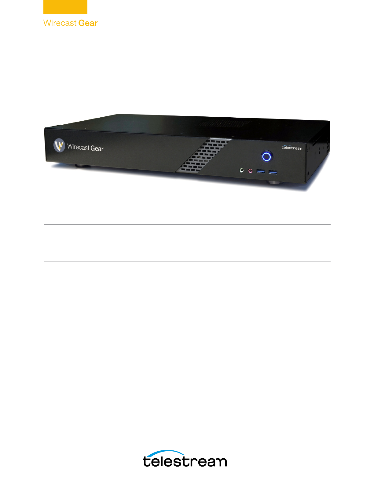
WC Gear Panels Introduction The following topics describe the Wirecast Gear front and rear panels. Note: Please do not make any connections just yet. First, read the panel and connector descriptions and then proceed to the Installation of WC Gear topic for steps to install and connect to the unit. Wirecast Gear is available in HDMI and SDI configurations. Both configurations share the same front panel features, but each configuration has a unique rear panel.
WC Gear Panels Front Panel Front Panel Wirecast Gear has the following connectors on the front panel. 1. Power Button 4. USB 3.0 2. Line Out (green) 3. Mic In (Pink) 1. Power Button This button turns the power on and off. When on, a blue light is displayed. 2. Line Out (Green) Use this output for headphones or a speaker system. You can also connect front speakers in a 4/5.1/7.1-channel audio configuration. 3. Mic In (Pink) Use this input for Microphones.
WC Gear Panels Rear Panel Rear Panel The Rear Panel connectors have the following functionality. 1. PS/2 Keyboard/ Mouse Port 2. SMA Antenna Connectors 3. RJ-45 LAN Ports 4. Center/Subwoofer Speaker Out 5. Rear Speaker Out 6. Line In 7. Line Out 8. Mic In 13. DVID Port 12. HDMI Output Ports 11. USB Type-C™ Port 9. Optical S/PDIF Out 10. USB 3.0/2.0 Ports 1. PS/2 Keyboard/Mouse Port Use this port to connect a PS/2 mouse or keyboard. 2.
WC Gear Panels Rear Panel Differences CAUTION: When removing any mic cable, pull it straight out from the connector to prevent causing a short inside the cable connector. 9. Optical S/PDIF Out Connector This connector provides digital audio out to an external audio system that supports digital optical audio. Before using this feature, ensure that your audio system provides an optical digital audio in connector. 10. USB 3.0/2.0 Port The USB 3.0 port supports the USB 3.
WC Gear Panels Rear Panel Differences Model 210/220 Rear Panel with SDI BNC 17 SD/HD/3G-SDI BNC Input Connectors SDI 4 SDI 2 SDI 3 SDI 1 Model 230 Rear Panel with SDI BNC and Ref Input SD/HD/3G-SDI BNC Input Connectors REF SDI 1 SDI 2 SDI 3 SDI 4 Note: The default SDI number assignment on the model 230 are out of order and differ from the numbering of the model 220.
WC Gear Panels Rear Panel Differences
Installation of WC Gear Introduction This section shows you how to install WC Gear. This includes physical mounting and wireless connections. Note: Before installing WC Gear, read through the section on WC Gear Panels. Topics Physical Mounting Wireless Connections Physical Mounting Wirecast Gear comes configured for table-top use with the included feet pre-attached.
Installation of WC Gear Wireless Connections Note: The Wirecast Gear system is configured to work with up to three displays. 1. If you plan to use Wifi, connect the antenna to the two jacks and position the antenna as desired. 2. If available, plug a network cable into one of the available RJ45 Ethernet jacks. Note: After it is powered on, Wirecast Gear will attempt to automatically connect to your installed network configuration (via LAN).
Installation of WC Gear Wireless Connections 7. Insert the USB dongle into a USB port on the front or back of the WC Gear box. Front USB ports Rear USB ports 8. Turn the keyboard and mouse on, using the power switch on each. 9. After all connections have been made, plug in the attached power cord to provide power to the unit. For input power requirements, see Specifications. 10. Turn on Wirecast Gear unit by pushing the power button on the front.
Installation of WC Gear Wireless Connections
Using WC Gear Introduction This section shows you how to get started using WC Gear and what to do when you boot up for the first time. Topics Getting Started First Time Boot Configuring the I/O Ports Getting Started To get started using Wirecast Gear, follow these steps: 1. If you aren’t familiar with Wirecast, read the Wirecast User Guide. You can download it from the Telestram web site at: http://www.telestream.net/telestream-support/wire-cast/help.htm 2.
Using WC Gear First Time Boot 1. Select Location, Language and Time. 2. When the Microsoft License Acceptance displays, read and click Accept.
Using WC Gear First Time Boot 3. Unless you have a specific requirement, click Use Express settings. 4. When the Create Account window displays, enter your user name and password and click Next. After a brief period of configuration, your Wirecast Gear will boot for the first time into Windows 10.
Using WC Gear Configuring the I/O Ports Configuring the I/O Ports Note: This section applies only to Wirecast Gear model 230. Introduction This section demonstrates how to setup the individual SDI connectors on the Blackmagic DeckLink Duo card. This enables the card to capture from all four inputs simultaneously in Wirecast. Setup To configure the SDI connectors on the Blackmagic card, follow these steps: 1. Press the Windows key and the “S” key together, to open the search window.
Using WC Gear Configuring the I/O Ports 2. When the setup window displays, logical input (1) is selected. Click on the configure button in the middle of the window to setup this logical input. Logical input (1) Click configure button 3. When logical input (1) setup window displays, click the Connectors tab.
Using WC Gear Configuring the I/O Ports 4. When the connector tab window displays, select connector SDI 1 from the dropdown menu, then click Save. Select SDI 1 Click Save 5. When the setup window displays, click the right arrow to select the setup page for the DeckLink Duo (2) input. Then click the Configure button in the center of the page to open the properties for logical input (2).
Using WC Gear Configuring the I/O Ports 6. Click the Connectors tab. Click Connectors tab 7. select connector SDI 3 from the drop-down menu, then click Save. Select SDI Click Save 8. Check logical inputs (3) and (4) to make sure they are assigned to SDI 2 and SDI 3, and not to a dual connector setting like “SDI 3 & SDI 4”. NOTE: Even though you are configuring logical input (2), you are assigning physical connector SDI 3 to it. The logical input numbers are displayed in parentheses, as “(2)”, etc.
Using WC Gear Configuring the I/O Ports But they are also displayed as selections in Capture Devices of the Shot Selection menu: Logical input numbers The physical SDI connectors are identified by “SDI 1”, etc. (See “Model 230 Rear Panel” on Rear Panel Differences for details). Reference Input The Reference Adjustment enables you to set the timing of the video outputs relative to the reference input signal. This is often used when the video output needs to be synced up with other video outputs.
Troubleshooting and Updating WC Gear Introduction This section shows you how to troubleshoot Wirecast Gear and how to get updates Topics General Drive Initialization Windows Update Issues General If your Wirecast Gear computer does not operate as expected, the following tips may provide assistance. CAUTION: Wirecast Gear is a sealed device, with no serviceable parts and no internal peripheral bays.
Troubleshooting and Updating WC Gear Drive Initialization Drive Initialization If you have received a Wirecast Gear unit and it is missing the secondary hard drive in Windows, but you can see it in Disk Management (right click on the start button, choose disk management), the drive is just in need of initialization. To do this, follow these steps: 1. Open Disk Management, right click the partition you need to format (partition D), then select Format. 2.
Troubleshooting and Updating WC Gear Windows Update Issues Your drive is now accessible in Wirecast and Windows. Windows Update Issues If you receive an question mark (?) with a yellow exclamation mark next to the capture devices, you may be experiencing a Microsoft Windows update issue. Question Mark Microsoft issued a statement updates will cause Windows computers (including Wirecast Gear) to lose their drivers to capture devices.
Troubleshooting and Updating WC Gear Windows Update Issues
Support for WC Gear Introduction This section shows you how to obtain customer support for WC Gear and how to make returns. Topics Obtaining Support | Information | Assistance Return Merchandise Authorization (RMA) Procedure Obtaining Support | Information | Assistance Support options for your Wirecast Gear are listed and briefly described below. Provide your organization name, and contact information, and the serial number of the affected unit.
Support for WC Gear Obtaining Support | Information | Assistance Support Resources Details and Contact Information Reseller Support If you purchased your Wirecast Gear from a reseller and did not also purchase GearCare Premium Support, please contact your reseller for product support. Telestream WC Gear Support Customers who bought Wirecast Gear directly from Telestream may request support as outlined below. • Support Web Site: http://www.telestream.net/ telestream-support/Wirecast-Gear/support.
Support for WC Gear Return Merchandise Authorization (RMA) Procedure Return Merchandise Authorization (RMA) Procedure If your Wirecast Gear needs service of any kind, see Obtaining Support | Information | Assistance on the previous page for contact information. If you are instructed by Telestream Support to return your Wirecast Gear, follow the procedure below. Please do not return a Wirecast Gear unit unless you receive an RMA number from Telestream first.
Support for WC Gear Return Merchandise Authorization (RMA) Procedure
Regulatory Compliance Statements Introduction This section presents the Regulatory Compliance Statements for the Wirecast Gear models 110, 210, 220 and 230.
Regulatory Compliance Statements Federal Communications Commission (FCC) Compliance Notices identification label of your device is listed in the manufacturer's OEM Regulatory Guidance document at URL http://www.telestream.net/pdfs/regulatory/ Gear-regulatory-guidance.pdf, or contact Telestream directly.
Regulatory Compliance Statements Federal Communications Commission (FCC) Compliance Notices RF Radiation Exposure & Hazard Statement To ensure compliance with FCC RF exposure requirements, this device must be installed in a location such that the antenna of the device will be greater than 20 cm (7.8 in.) from all persons. Using higher gain antennas and types of antennas not covered under the FCC certification of this product is not allowed.
Regulatory Compliance Statements Canadian ICES Statements Canadian ICES Statements Contains IC: 1000M-8260NG This device complies with ICES-003 and RSS-247 of Industry Canada. Operation is subject to the following two conditions: 1. This device may not cause interference, and 2. This device must accept any interference, including interference that may cause undesired operation of the device. Ce dispositif est conforme aux normes NMB003 et CNR-247 d'Industrie Canada. 1.
Regulatory Compliance Statements European Union and European Fair Trade Association Regulatory Compliance fournies dans ce manuel. Cet émetteur ne doit pas être co-implanté ou exploité en conjonction avec toute autre antenne ou transmetteur. Deployment Statement This product is certified for indoor deployment only in the 5150 - 5250 MHz band. Do not install or use this product outdoors in that frequency band in Canada.
Regulatory Compliance Statements European Union and European Fair Trade Association Regulatory Compliance LUXEMBOURG, MALTA, NETHERLANDS, POLAND, PORTUGAL, ROMANIA, SLOVAKIA, SLOVENIA, SPAIN, SWEDEN, UNITED KINGDOM, ICELAND, LICHTENSTEIN, NORWAY, SWITZERLAND Declaration of Conformity Declaration of Conformity is marked by this symbol: This indicates compliance with the Essential Requirements of the Radio Equipment Directive (RED) of the European Union (2014/53/EU).
Regulatory Compliance Statements Warning and Caution Messages Attention! Ceci est un produit de Classe B. Dans un environnement domestique, ce produit risque de créer des interférences radioélectriques, il appartiendra alors à l'utilisateur de prendre les mesures spécifiques appropriées.
Regulatory Compliance Statements Warning and Caution Messages Warning Symbol Hazard Symbol Caution Symbol Before operation please read the following: Warning! Read and follow all warning notices and instructions marked on the product or included in the documentation. Warning! Do not use this device near water and clean only with a dry cloth. Warning! Do not block any ventilation openings or place anything on top of the device to ensure proper CPU cooling.
Regulatory Compliance Statements Warning and Caution Messages Warning! Since the Mains plug is used as the disconnection for the device, it must remain readily accessible and operable. Warning! Protect the power cord from being walked on or pinched particularly at plugs, convenience receptacles, and the point where they exit from the device. Warning! Do not open the chassis. There are no user-serviceable parts inside.
Regulatory Compliance Statements Warning and Caution Messages