
User Manual
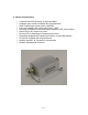
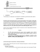

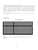

Table Of Contents
- SMARTAMP TM
- User and Installation Manual
- User and Installation Manual i
- 1. General Product Description
- 2. Background
- 3. Major Parameters
- 4. Salient Characteristics:
- 5. Installation:
- 6. DC Power Injector Connections, Indicators and labels:
- 7. Amplifier Connections, Indicators and Labels:
- 8. Functioning:
- 9. Specifications:
- 10. LIMITED WARRANTY
Page 7
“To Amplifier” Connection:
This “N” Female connector connects to the amplifier on the mast via the transmission
cable.
LED: Green LED indicates DC power on.
DC Power Supply:
The power supply provided with the unit is universal type, 110/220
V AC to 12 VDC converter. This has been tested for quality and
performance. If a different 12V DC adapter has to be used make sure
it is provided with center positive 2.5mm jack and minimum of 1.2
Amp rated capacity.
7. Amplifier Connections, Indicators and Labels:
“TO DC Injector” Connection:
This “N” Female connector is connected to the DC Power Injector via the transmission
cable.
“TO Antenna” Connection:
This “N” Female connector connects to the antenna with a short length of coax cable.
LED:
This LED indicates three states:
1. Transmit = Green
2. Receive = Red
3. High speed Tx / Rx switching = Orange
8. Functioning:
The unit operates automatically and no user adjustments are required.
This amplifier is designed for 2.4 GHz radios using Time Division Duplex (TDD) mode of
operation. It is equipped with a high speed Tx / Rx switch, that detects transmit signal and
switches to transmit mode within 600 ns. In the absence of any transmit signal the unit stays in
receive mode. If used with a radio devices using separate bands for transmit and receive in a
true full duplex mode, the amplifier would not work.
9. Summary: