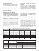
505 Audio Line Driver Service Manual 1505 MIXER/ LINE DRIVER CH 1 CH 2 CH 3 MUTE CH 4 SPKR PTT HANDSET MIC SPEAKER CH 1 CH 2 CH 3 Tx CH 4 CH 1 CH 2 CH 3 Rx CH 4 LEVEL ADJUST 098-0355
1. 2. 3. 4. 5. 6. 7. 8. Table of Contents General . . . . . . . . . . . . . . . . . . . . . . . . . . . . . . . . . . . . . . . . . . . . . . . . . . . . . . . . 1 Standard Features . . . . . . . . . . . . . . . . . . . . . . . . . . . . . . . . . . . . . . . . . . . . . . . . 1 Installation . . . . . . . . . . . . . . . . . . . . . . . . . . . . . . . . . . . . . . . . . . . . . . . . . . . . . . 1 Connections . . . . . . . . . . . . . . . . . . . . . . . . . . . . . . . . . . . . . . . . . . . . . . . .
.3 Mounting This card is intended to be mounted in a Tellabs Type 10 or equivalent open frame rack. To avert erroneous operation, don’t install the card adjacent to equipment that generates high temperature or electromagnetic radiation. Always provide an appropriate service loop on interconnecting cables. 3.4 Access for Installation/Servicing When installing into a Tellabs Type 10 or equivalent open frame rack, ensure the front and rear of the rack have clear access for card installation and wiring.
. Connections 4.2 Signal Connections and Card Edge Connector Pin Assignment Warning - High Voltage! Remove Power Before Servicing! High voltage may be present on this card (if used for switching phone lines with superimposed dc current signaling) which could cause serious injury or loss of life. Only qualified personnel familiar with this type of circuitry should work on this equipment. To prevent injury, damaging the card or other equipment, remove power before making connections.
4.3.2 Microphone Jumpers Depending on which microphone you are using, the following jumpers must be installed: 4.3.5 Parallel Transmit Line Impedance Matching If the occasion arises where the transmit line output must operate in parallel with another line terminating device, an impedance mismatch to the phone line will result. To maintain a 600Ω termination, it will be necessary to create a resistive pad on the output of the 1505 line driver. A similar pad must be installed in each parallel device.
5.2 Operating Capabilities The 1505 accepts up to four balanced or unbalanced inputs, switch selectable by the user, to four balanced line driver outputs. These inputs are also externally mutable by switched low inputs at the rear panel connection. In addition, the module will accept a microphone or handset input through the front panel jack or the rear panel connector. 4.
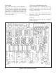
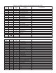
Table 4. Card Edge Connector Pin Assignments (Solder Side) Card Edge 1 3 5 7 9 11 13 15 17 19 21 23 25 27 29 31 33 35 37 39 41 43 45 47 49 51 53 55 Alt #1 Conn A B C D E F H J K L M N P R S T U V W X Y Z A B C D E F Alt #2 Conn A B C D E F H J K L M N P R S T U V W X Y Z AA BB CC DD EE FF Function User Connection Ch #4 Rx Bal. Line In (-) Ch #4 Rx Mute Ch #4 Rx Bal. Line In (+) Ch #4 Rx UnBal Line In Ch #3 Rx UnBal Line In Ch #3 Rx Bal Line In (+) Ch #3 Rx Bal. Line In (-) Ch #2 Rx Bal.
6. Theory of Operation 6.3 Compression Limiter Circuit This circuit amplifies and limits the output of the receive inputs ensuring uniform audio levels from all channels regardless of the input level received from the external line input. For a 30 dB gain, once achieving the compression level, only a 3 dB increase in output level, without distortion, results in the circuit. Normally the input level, at 0 dB, allows the limiter to amplify in a linear fashion below that level, and above the 0.
8
6.8 Indicators The speaker and each receive input channel can be muted. The front panel has an indicator to visibly indicate which channels have been muted. The front panel also has a PTT LED which is illuminated when the PTT switch has been activated on the handset or microphone. 6.5 Microphone Input A microphone input is available through a jack on the front panel. It allows connection of a handset or palm type microphone through a standard modular phone connection.
7. 1505 Specifications Operating Temperature Range: . . . . . . . . . . . . . . . . . . . . . . . . . . . . . . . . . . 0°C to 60°C Power Requirements: . . . . . . . . . . . . . . . . . . . . . . . . . . . . . 11 to 16 Vrms semi-regulated, 250 mA nominal 600 Ω/10K Ω Balanced Receive Line Input Level: . . . . -30 dBm to +10 dBm, adjustable 10 K Ω/10 K Ω Unbalanced Receive Input Level: . . . . . 0.025 Vrms to 2.5 Vrms, adjustable 10 K Ω/10K Ω Mic Input Sensitivity:. . . . . . . . . . . . . . . 0.
8. 1505 Parts List Part No. Description 012-0085 031-0226 065-0463 071-0566 102-0120 PCB SUB ASSY 1505MIX/LINE TEXT SPEC 1505 AUD MIX/LD PCB 1505 AUD MIX/LIN DR SCHEMATIC 1505 MIX/LINE D CAP CER 20P 5% 50V S2L 102-0290 CAP CER100P S2L 5% 50V 102-0400 CAP CER 330P S2L 5% 50V 102-0420 103-0001 CAP CER 390P S2L 5% 50V CAP CER.001 10% 50V Y5P 104-0767 CAP TANT 1UF 35V 110-1340 CAP CER .
Part No. Description Ckt Sym Part No. Description 134-2837 RES RN55D 15.
Part No. Description 286-1766 CONN JUMPER PLUG 286-1772 286-1964 Ckt Sym Part No. Description Ckt Sym JP1 JP2 JP3 JP4 JP5 JP6 JP7 JP8 JP9 JP10 JP11 JP12 JP13 CONNECTOR 36PIN STRIP TIN JP1 JP2 JP3 JP4 JP5 JP6 JP7 JP8 JP9 JP10 JP11 JP12 JP13 TEST POINT YELLOW .
NOV. 2000 8601 East Cornhusker Highway, Lincoln, Nebraska, 68507 Phone: (402) 467-5321 / (800) 752-7560 Fax: (402) 467-3279 E-mail: vega @telex.com, Web: www.vega-signaling.com Printed in U.S.A.