Application Guide Kenwood Radio Series 80, 90 and 150/180 To IP-223 November 4, 2005 P/N AN-VEGA-1 Rev D
II IP-223 to Kenwood Radios Table of Contents 1 General ................................................................................... 1 2 Setup ....................................................................................... 1 2.1 TK-x150/180 Model Cable Assembly:........................................................................... 1 2.2 TK-x80 Model Cable Assembly: .................................................................................... 1 2.2.
IP-223 to Kenwood Radios 1 1 General The application note is intended to show how to assemble the cable and setup the hardware of the IP223 for channel change and FleetSync applications using Kenwood radio. 2 Setup 2.1 TK-x150/180 Model Cable Assembly: NOTE: There are differences between the TK-x150 and TK-x180 radios DB25 connectors. If COR is used, pin 20 (TK-x150 an output only) will be programmed for that function and the cable will route that signal to the IP-223.
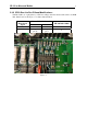
IP-223 to Kenwood Radios 2 2.2.1 IP223 Rev F or higher Board Configuration: Set the jumper J35 to B position for line 1 and the jumper J26 to B position for line 2 IP223 Serial Signal TXD RXD IP223 DB9 Line 1 Line 2 9 4 1 6 KCT-19 Accessory Conn. 14 15 2.2.2 IP223 Rev A to Rev E Board Modifications: Lift Pin 12(line 1) or pin 9(line 2) of U45 according to the line selected and solder to its PCB Pad. Please refer to the Figure 1 for better demonstration.
IP-223 to Kenwood Radios 3 2.3.2 IP223 Rev A to Rev E Board Modifications: Lift Pin 12(line 1) or pin 9(line 2) of U45 according to the line selected and solder to its PCB Pad. Please refer to the Figure 1 for better demonstration.
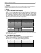
IP-223 to Kenwood Radios 4 2.4 IP223 Configuration: Setup the desired IP223 line for Kenwood radio control at the following screen: 2.4.1 Per-line setup screen C B A Choose radio model in the Serial Port Mode box (A). Change Serial Port Parameter box to 9600.N.8.2 (B). Configure Talk Group and CHAN fields for channel change capability (C ). 2.4.
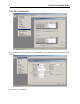
IP-223 to Kenwood Radios 2.5 Radio Configuration 2.5.
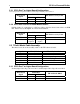
6 IP-223 to Kenwood Radios 2.5.2 TK-x90 Series Program Function Port, Input screen for Ext PTT in Radio 1 Al1.
IP-223 to Kenwood Radios Program Function Port, Output screen for COR in Radio 1 AO1.
8 IP-223 to Kenwood Radios 2.5.3 TK-x150/180 Series Program Function Port, Aux Input for External PTT in AUX Input4 location and COR in AUX Output1.
IP-223 to Kenwood Radios 9 For the TK-x180, the AUX programming screen is different. Please note that the same interface cable is used for both the TK-x150 and TK-x180 radios. If COR is used, IP-223 Jumper 8 (Line 1) or Jumper 30 (Line 2) will have to be placed in a neutral position for the Aux port pin 20 on the TK-x180 to function properly as COR. TK-x180 auxiliary setup screen Suggestions or Comments We’d appreciate your input.