
User Guide
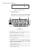
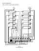
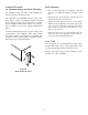
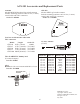

Connec tions, Fuses and In di ca tors
-2-
1.
Power/Over heat Light -
Green - The unit has power.
Red - The unit has over heated and the combiner am pli fi ers
have shut down. There is a sen sor on the combiner amplifier
heatsink that senses if the heat rises above 75º C (167 F).
2.
DC Out let Fuses - 5 Amp, SlowBlow, 250 VDC. Size is 3AG.
3.
IEC Power In let with Fuse - IEC-320 power in let with a 10
Amp, 250 VDC Fuse. Size is 5mm by 20mm.
4.
DC Power Out put Jacks - Threaded 5.5mm x 2.1mm Jacks. 12
VDC up to 5 Amps is avail able at each jack.
5.
Re ceive An tenna Jack - This TNC fe male con nec tor is where
the re ceive an tenna con nects.
6.
Re ceive Split ter Jacks - These ten TNC Fe male con nec tors are
the out puts for the re ceive sig nals. NOTE: All un used jacks
should be ter mi nated with 50 Ohm loads (See ac ces so ries
listed at the end of this doc u ment).
7.
Trans mit Combiner Jacks - These ten TNC fe male con nec tors
are the in puts for the trans mit ters.
8.
Trans mit An tenna Jack - This TNC fe male con nec tor is where
the trans mit an tenna con nects.
CS-
A01
1
UHF Antenna Splitter/Combiner
POWER - GREEN
OVERHEAT - RED
RadioCom
TM
by
Telex
R
1
Fig ure 1 ACS-101 Front View
Fig ure 2
ACS-101 Rear View
TRANSMIT
ANTENNA
FUSE
5A SLOW BLOW
DC OUT
12V 5A
FUSE
5A SLOW BLOW
DC OUT
12V 5A
RECEIVE
ANTENNA
TRANSMIT
RECEIVE
8
2
4
3
5
2
4
7
6