
User Guide
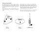

An tenna Place ment
for Op ti mum Range and Rack Mount ing
For max i mum range and when rack mount ing, the
an ten nas must be re motely lo cated.
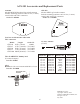
The ALP-450 and ALP-600 an ten nas come com -
plete with a va ri ety of mount ing hard ware and 10
feet (3 me ters) of low loss co ax ial ca ble. A com bi -
na tion mount ing bracket with 10 feet of co ax ial ca -
ble is avail able for 1/2 wave an tennas (Model No.
AB-2).
An tennas should be placed in a lo ca tion with a clear
“sig nal path” to the beltpacks. This “path” should
be as short and free of ob struc tions as pos si ble. Ob -
struc tions, such as walls ceil ings, and metal ob jects,
will re duce range and per for mance.
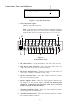
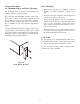
Rack Mount ing
·
Rack mount brack ets are sup plied with the
ACS-101. To at tach the brack ets, pro ceed as fol -
lows:
·
Align the rack mount bracket with the holes on
the side of the unit. See Fig ure 8.
·
In stall flat head ma chine screws in two holes.
Tighten se curely. Re peat on the other side of the
unit. For best align ment, per form the above
steps while the unit and rack brack ets are set -
ting on a flat sur face.
·
In sert the unit into a 19" rack en clo sure and in -
sert four screws (not sup plied) in each cor ner of
the rack mount brack ets and se cure.
Coax Ca ble
For best re sults, it is rec om mended that ca ble losses
be kept un der 4 dB. (Ev ery 3 dB of sig nal loss re sults
in a sys tem op er at ing dis tance re duc tion of 25%.
See the ac ces so ries sec tion of this man ual for spe -
cial low loss ca ble as sem blies.
-5-
Fig ure 8
Rack Mount Brackets