MS-2002 Master Station and Power Supply User Manual 9350-7749-000 Rev J 1/2010
PROPRIETARY NOTICE The product information and design disclosed herein were originated by and are the property of Bosch Security Systems, Inc. Bosch reserves all patent, proprietary design, manufacturing, reproduction, use and sales rights thereto, and to any article disclosed therein, except to the extent rights are expressly granted to others.
Important Safety Instructions 1. Read these instructions. 2. Keep these instructions. 3. Heed all warnings. 4. Follow all instructions. 5. Do not use this apparatus near water. 6. Clean only with dry cloth. 7. Do not block any ventilation openings. Install in accordance with the manufacturer’s instructions. 8. Do not install near any heat sources such as radiators, heat registers, stoves, or other apparatus (including amplifiers) that produce heat. 9.
Table of Contents INTRODUCTION ............................................................................................................................................................................................ 7 Description .................................................................................................................................................................................................... 7 Features ......................................................................
CHAPTER 1 Introduction Description The MS-2002 is a complete 2-channel master station and system power supply (24VDC, 2Amps total power) in a single unit. Simply plug it into any AC power outlet from 100 to 240 volts, add a microphone or headset, connect intercom stations to the back panel, and you’re ready to communicate. It has both 1- and 2-channel connectors, so you do not have to add a separate breakout box if you want to mix 1- and 2-channel stations.
Features FIGURE 1. MS-2002 Reference View. Dynamic-Mic Headset Connector - Accepts headsets with monaural headphones and either a balanced or unbalanced dynamic microphone. 2. Panel Mic / Electret-Mic Headset Connector - Accepts an electret gooseneck microphone, such as the Telex Model MCP-90-XX. The model MCP-90 series panel mic connector is a 1/4” stereo plug, with a threaded shaft for easy installation. 3. Volume Control - Adjusts headphone volume only. 4.
CHAPTER 2 Installation Configuration Pre-check Before connecting the MS-2002 make sure it is properly configured for you intended usage. The locations of the configuration switches are shown in Figure 2. To access internal switches, do the following: > Remove three (3) screws from the top cover and three (3) screws from the bottom portion of each side. FIGURE 2.
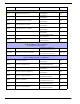
Switch # Description Settings Default DIP SWITCH SW1 (INTERNAL) SW1-1 Headset Microphone Type On: Unbalanced Off: Balanced Off SW1-2 Call Signal Send, channel 1 On: Enabled Off: Disabled On SW1-3 Call Signal Receive, channel 1 On: Enabled Off: Disabled On SW1-4 Call Signal Send, channel 2 On: Enabled Off: Disabled On SW1-5 Call Signal Receive, channel 2 On: Enabled Off: Disabled On SW1-6 Mic Kill Signal Send On: Enabled Off: Disabled Off SW1-7 Program 2 On: Interrupt During Tal
Headset Microphone Type Selection DIP Switch SW1-1 applies only to a dynamic-mic headset connected to the dynamic-mic headset jack on the front panel. If the headset specifications indicate the microphone type is balanced, or if you are unsure, leave this switch in the off (default) position. If the specifications indicate an unbalanced microphone, set SW1-1 to on. NOTE: For best results in noisy environments, a noise canceling (directional or cardioid) microphone is highly recommended.
Monaural or Binaural Operation DIP Switches The MS-2002 can be used with a single speaker or monaural headphones (single- or double-sided) for monaural operation. In this case, all audio signals are combined and sent to the headphones and the front panel speaker. The combined signals also go to the Speaker 1 jack on the back panel. The MS-2002 can also be used with two (2) speakers for binaural operation. In this case, channel 1 is sent to the Speaker 1 jack and channel 2 is sent to the Speaker 2 jack.
Mounting The MS-2002 mounts in a standard 19-inch equipment rack and is 1 RU (Rack Unit) high. When mounting the MS-2002, install the supplied black face plates on the appropriate side. The face plates should be mounted with the grooves on the top. NOTE: You must perform the sidetone adjustment (page 10) after all components are connected. With the MS-2002 being rack mounted, you may not be able to access the sidetone trimmers.
Cables The numbers below correspond to the cable numbers in the connection drawings on the following pages. • 1-channel intercom cable. Sold Separately. Use Telex ME cables, below. Or, build per Figure 7 on page 19. ME-25: 25’ (7.6 m) cable with Male and Female 3-pin XLR connectors. ME-50: 50’ (15.2 m) cable with Male and Female 3-pin XLR connectors. ME-100: 100’ (30.4 m) cable with Male and Female 3-pin XLR connectors. NOTE: When connecting from the MS-2002 to a TW-7W, keep cables as short as possible.
. FIGURE 3. MS-2002 Monaural Master Speaker Station Configuration. Agood configuration for smaller intercom systems when you want to operate the MS-2002 as a master speaker station, with one (1) speaker to monitor both intercom channels. In this configuration, the Combine/Isolate switch is set to the Isolate position. With this setting, the two (2) intercom channels are completely separated. The MS-2002 dip switches are set to monaural operation so that both intercom channels are heard in the speaker.
FIGURE 4. MS-2002 Binaural Master Speaker Station Configuration. A good configuration for smaller intercom systems when you want to operate the MS-2002 as a master speaker station, with a separate speaker for each intercom channel. Make sure the MS-2002 intercom DIP switches are set for binaural speaker operation on page 12. Also, set the Combine/Isolate switch to the Isolate position. With this setting, the two (2) intercom channels are completely separated.
FIGURE 5. MS-2002 Typical Speaker Station and Belt Pack Connections. Typically, a headset is connected to the front panel of the MS-2002, and the DIP switches are set to the monaural operation (default setting) so both intercom channels are heard in the monaural headphones (binaural headphone operation is not supported). Beltpacks use less power than speaker stations, and you can daisy-chain more of them on a single cable run. Avoid very long cable runs with daisy-chained speaker stations.
FIGURE 6. External Audio Input and PA Output. You can connect two (2) audio sources to the Program Inputs connector: one (1) for each channel. Audio sources can be directly connected with a user-supplied DB9M connector. For more information on the program input connector specifications, see “Specifications” on page 15. However, a more convenient method is to use an XP-USPG Breakout Panel as shown. The XP-USPG also interfaces the PA jack of the MS-2002 to a standard, 2-pin XLR audio cable.
TYPICAL 1-CHANNEL CABLE WIRING 3 2 Pair 1 3 2 1 Pair 2 1 (Both wires) Shield Shield Cable Type: 22AWG Stranded, 2-Pair Twisted-wire, with Shield Connector Type: 3-Pin XLR Audio (Neutrik or Switchcraft)* Pin 1: Common Denotes twisted pair. Pin 2: Channel Audio / Power Pin 3: Channel Audio / Power Denotes shield.
CHAPTER 3 Operation and Specifications Power-Up Check To power-up the MS-2002, do the following: > Plug in the MS-2002. When power is first applied to the MS-2002, it performs a power-up reset, in which the front panel indicators cycle through all of their possible colors and then turn off. This verifies the general operation of the intercom station and indicators. The MS-2002 also reads the settings of all DIP switches at this time and configures itself accordingly.
Sidetone Adjustment The MS-2002 uses full-duplex audio (the same as a conventional telephone line) where the talk and listen audio are sent and received on the same line. When you talk on a channel, you also hear your own voice back in the speaker or headphones. This is called sidetone. If you are using the MS-2002 with a microphone and speaker, sidetone could cause unwanted feedback, since the microphone may pick up your returned voice audio and reamplify it.
Voice-Activated Microphone (VOX) Setup If you are going to use VOX, you must adjust the VOX level for proper operation. If the VOX level is too low, room noise activates the microphone. If the VOX level is too high, the microphone does not activate when you begin talking. To check and set the VOX level, do the following: 1. If you are using a headset, tap the Headset key twice to turn on headset VOX. OR If you are using a panel microphone, tap the Panel Mic key twice to turn on panel mic VOX.
Volume Adjustment To adjust the volume, do the following: > If you are using a headset, adjust the intercom listen level with the left Volume control on the front panel of the MS2002. OR If you are using a speaker, adjust the intercom listen level with the right Volume control next to the speaker. External speakers require their own volume controls. Receiving Calls When there is an incoming call signal on a channel, the Call key for that channel flashes red.
All Talk You can talk to all intercom stations that currently have their listen keys activated. This applies to both channels of the MS-2002, as well as all talk channels of any connected EMS-4001 Expansion Stations. To use All Talk, do the following: 1. If you are using manual microphone activation instead of VOX, verify the proper microphone switch is turned on (either Headset or Panel Mic). 2. Press and hold the All Talk key while talking. 3. Release the key when finished.
Using Voice-Activated Microphone (VOX) If you use VOX, you do not have to insure the microphone key is turned on whenever you want to talk. To activate VOX, do the following: 1. Verify the Headset and Panel Mic keys are off. 2. If you are using a headset, tap the Headset key twice to turn on headset VOX. OR If you are using a panel microphone, tap the Panel Mic key twice to turn on panel mic VOX.
Specifications General Power Requirements: AC Input: 100-240VAC, 50/60Hz Channel Power: 24VDC nominal (12 to 30 VDC), 65 to 150mA MS2002 is capable of supplying 2 amps overall (1 Amp per channel) Pin 1 Pin 2 Pin 3 Pin 4 Pin 5 Pin 6 Pin 7 Pin 8 Pin 9 Ground Program 1 input low Program 2 input low NC NC Program 1 input high Program 2 input high NC NC Dimensions: 1.75” (44.5mm) high x 19” (483mm) wide x 10.31” (261.9mm) deep Weight: Approximately 4.5lb.
Connector Type: Uses same connectors as for balanced mode, above, but without pinouts modified by BAL/UNBAL switch on back panel as follows XLR-3 Unbalanced Configuration Pinouts Pin 1 Common Pin 2 +24 VDC input Pin 3 Intercom audio high XLR-6 Unbalanced Configuration Pinouts Pin 1 Common Pin 2 Local Power (12 to 15 VDC, 65 to 150mA) Pin 3 Channel 1 +24 VDC input Pin 4 Channel 1 Intercom audio high and DC call Pin 5 Channel 2 +24 VDC input Pin 6 Channel 1 Intercom audio high and DC call PA
Quick Reference Description Action Reset MS-2002 Press All Talk and Listen 1 Reset EMS-4001 Press All Talk and Listen 5 Test signal on Press All Talk and PA, then tap Call Test signal off Tap Call, then tap any other key Mic latched on Tap Headset or Panel Mic (key is green) Mic latched off Tap Headset or Panel Mic Mic momentary on Hold Headset or Panel Mic VOX mode on Tap twice: Headset or Panel Mic VOX mode off Tap Headset or Panel Mic All talk on Hold All Talk when Headset or Panel M