
Wireless Intercom System Service Manual


ALIGNMENT PROCEDURE:
)
Equipment Required:
D Signal Generator
D Audio Generator
D Deviation Meter
D Audio Voltmeter
1.
Connect the audio generator to the AUX
IN
jack
and set the output
to
20 mV at 1
KHz.
2.
Select the AUX pushbutton on
therront
panel.
3.
Adjust VR601 (locatedjust under the
I1C
push-
button
on
the
front
panel)
to
maximum
counterclockwise.
4.
If
the base is configured
for
an RTS intercom
connect the load
to
the
llC
jack pn the rear
panel.
5.
Connect the audio voltmeter to the AUX OUT
0
jack on
the
rear panel.
6.
Adjust VR101 for a minimum reading.
7.
Disconnect the generator and meter from the
AUX jacks and de-select the AUX pushbutton
on the front panel.
8.
Connect the signal generator to the Receive
Antenna jack. Set the deviation to
± 3 KHz at
1
KHz.
Setthe output to 1 m
V.
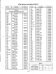
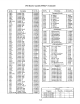
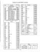
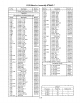
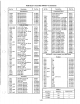
Setthe frequen-
cy to the channel 1frequency listed in the chart
of
the receive board alignment.
-
I
9.
Select the channel 1 pushbutton on the front
panel.
10.
Connect
the
deviation
meter
to the
ANT
TRANS jack.
11.
Connect the audio voltmeter to U106 pin
7.
12A. On version 1 and 2 audio boards, adjust VR102
for
300 mV
of
audio.
12B. On version
3 and later audio boards with ver-
sion 1 transmit boards, adjust VR102 for 1 volt
of
audio.
12C. On version
3 and later audio boards with ver-
sion 2 transmit boards, first move the audio
voltmeter to
U501 pin 16 (on the transmit
board). Then adjust VR102 for 140 mV
of
audio.
13. Adjust VR501 for
± 4.2 KHz deviation.
3-29/3-30 Blank