Model C-2002 Radio Control Console Technical Manual November 8, 2005 P.N.
i Remote Control Console Table of Contents 1 INTRODUCTION ...............................................................................................................................................1 2 CONTROLS AND INDICATORS.....................................................................................................................2 2.1 FRONT PANEL ................................................................................................................................................
ii Vega’s C-2002 7.3 LEVEL MENU SCREEN ..................................................................................................................................15 7.3.1 Menu 1 - Line Level Settings ...............................................................................................................16 7.3.1.1 RX Input Level Screen .......................................................................................................................................... 16 7.3.1.
Remote Control Console iii MUTE BUTTON .............................................................................................................................................27 7.7 7.7.1 Per line Mute button Setup ..................................................................................................................27 7.7.2 Incoming Select Call DTMF String Setup ...........................................................................................28 7.
iv Vega’s C-2002 Table of Figures Figure 1 Front Panel Diagram .....................................................................................................................2 Figure 2 Rear Panel Diagram.......................................................................................................................3 Figure 3 Rear Panel Pinout ..........................................................................................................................
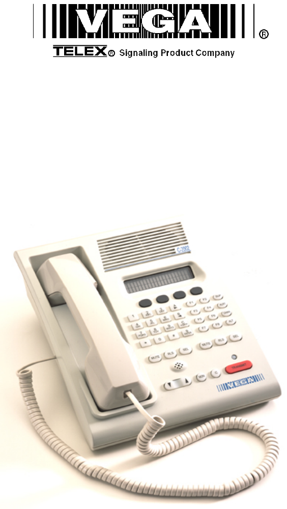
Remote Control Console 1 1 Introduction The model C-2002 is a full-featured Two-Line, multi-format, and self-contained desktop radio control console. Its sleek and modern look will compliment any surroundings. The C-2002 is a Digital Signal Processor (DSP) based design, allowing easy field programmability using the DTMF and soft keypads on the front of the console. Unlike other manufacturers’ equipment, no additional software is required to program the C-2002 console.
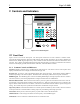
2 Vega’s C-2002 2 Controls and Indicators C-2002 Vu Muter Ln1-Fn2 1 A -> F1 F2 SUP B <- F3 F4 Alert WXYZ C F5 F6 Chan # D Enter F7 F8 ALT 2 3 ABC DEF 4 5 6 GHI JKL MNO 7 8 9 PQRS TUV * 11:08AM Ln2-Fn8 0 LINE 1 Mute RLS LINE 2 SEL MON Mute IC RLS SEL Transmit VOLUME Figure 1 Front Panel Diagram 2.1 Front Panel Figure 1 shows a view of the Front panel. The Front panel contains the user I/O.
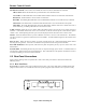
3 Remote Control Console Line Buttons LN1-LN2: Three buttons are available for each Line, SELect, RLS (Release) and Mute. SELect button: When the SEL buttons is pressed that line enters the Select mode Select LED: The Red LED under each LNx SEL Button indicates if the line is selected for transmit audio. RLS button: The RLS button is used to release a selected line. RLS LED: The blinking Red LED under each LNx RLS Button indicates receive audio activity on that line.
4 Vega’s C-2002 Line Port: The C-2002 is equipped with two single line jacks. The connector is a standard eight pin RJ-45. The pinout of the connector appears in Figure 3. The numbering of the pins is shown in Figure 3 for reference. In addition to the standard RX and TX pin pairs, the unit also can be supervised and supports cross mute functions. Pins 7 and 8 of the Line connector can be used as a form C closure relay for local control. Pins 7 and 8 form the closure during any PTT operation.
Remote Control Console 5 3 Operation 3.1 Selecting a line Selection of a line for transmit occurs when the “SEL” button is pressed and the LED under the switch lights, to transmit on both lines press the “ALT” button then the “SEL” button of the opposite line. 3.2 Releasing a line To release a selected line from transmit press the “RLS” button for the selected line. If the “RLS” button LED is blinking RX audio was present on the line during the last 10 seconds or the time preset in tech-mode. 3.
6 Vega’s C-2002 4 Line Setup and Description 4.1 INTRODUCTION/DEFAULTS 1 2 3 4 5 6 7 8 1) 2) 3) 4) 5) 6) 7) 8) Cross Mute I/O Supervisor I/O RX + TX +/ (RX + 2W) TX -/ (RX - 2W) RX Local GND/Local Connector View Figure 4 Line Connector Pin Out The Line interface for the C-2002 console provides communication with any standard tone remote system. Figure 4 shows the pin out of the line interface connector, which is on the rear panel (See Figure 2 and Figure 3). 4.2 FEATURE DESCRIPTION 4.2.
7 Remote Control Console 4.2.2 Supervisor Function C o nsole 1 : L ine 1 1 2 3 4 5 6 7 8 C o nsole 2 : C onsole 3 : L ine 1 L ine 1 1 2 3 4 5 6 7 8 1 2 3 4 5 6 7 8 L ine L ine + Figure 6 Supervisor Function Example. The Supervisor Function enables a console, such as the C-2002, which has the capability to drive this line, to disable all units on a particular line. This includes both PTT and RX audio. Its connection is similar to that of the crossmute function.
8 Vega’s C-2002 Console # 1 2 3 4 5 6 J8 Position A B B B B B Impedance 604 10k 10k 10k 10k 10k Impedance 604 569 539 511 486 464 Loss (dB) 0.0 -0.5 -1.0 -1.5 -1.9 -2.3 Level adjustment can be made to the receive audio by entering the setup mode or adjusting the RX level POT inside the C-2002. 4.2.6 TX Side Settings The C-2002 TX output circuitry has a DPDT relay that is used to connect and disconnect the TX output transformer from the TX line based on PTT status.
Remote Control Console 9 4.3 Level Adjustments 4.3.1 Transmit Side Adjustments The transmit audio consists of multiple audio sources – microphone audio, AUX input, function tones, and DTMF tones. Each audio sources is summed or generated in the DSP with the analog signal being generated on a single DAC. The following is a list of the potentiometers that affect the transmit path.
10 Vega’s C-2002 5 Hardware Overview The C-2002 is a Two-line, multi-mode console designed specifically for small to medium level system requirements. All functions are housed in a single small modern looking console. 5.1 C-2002 Console The C-2002 consists of the following sub-assemblies enclosed in the single case: Main Processing Board, Keypad PCB and Display. 5.1.1 Main PCB The Main PCB is mounted to the bottom of the enclosure using 4 #6 screws.
Remote Control Console 11 6 Theory of Operation The C-2002 is a Digital Signal Processor (DSP) based product. Because of this, many of the signals that once could be probed on older products, are handled within the DSP itself. This would include DTMF generators and decoders, notch filters, tone generators and decoders, and all of the audio summing. A great deal of the gain controls are included within the software of the DSP.
12 6.4 System Clock Generation Vega’s C-2002 The system clock is derived from a single 32.7680MHz Crystal Oscillator (Y1). The ADSP2189 DSP (U1) processor uses this clock to generate a 65.536MHz internal instruction clock rate. The system clock is routed to the Altera EPM7032AE44 PLD (U5) and divided into the signals necessary for audio processing. These signals include the MCLK (2.048MHz), SCLK (512kHz), LRCLK (8kHz) and FS (16kHz frame sync). Another signal generate by the PLD is B0 (U5-28).
13 Remote Control Console 7 Setup Mode 7.1 Tech Mode The tech mode allows a technician to program the internal settings of the C-2002 console. The tech mode is entered by pressing MUTE-F6-* simultaneously. The technician will be required to enter a PIN number to allow entry. See the section 7.4.4.1 on setting up the PIN number. The Opening Menu is displayed when tech mode is entered.
14 7.1.
15 Remote Control Console 7.1.
16 7.3.1 Vega’s C-2002 Menu 1 - Line Level Settings This screen is displayed after a line has been selected from the Level Menu Screen. The selected line number is shown on the display and the select LED for that line continues to blink. In this example Line 1 has been selected. PROG1 - Go to RX Input Level Screen. PROG2 - Go to LAM level setup. PROG3 - Go to Line Levels Screen. PROG4 - Return to Level Menu Screen. Line 1 level adjust RX LAM back PROG1 PROG2 PROG3 PROG4 7.3.1.
17 Remote Control Console 7.3.1.3.1 Mute Button Level Screen These parameters determine the level of Mute on a Per line bases. Mute Level = -10dB -10db dwn up back PROG1 – Resets level setting to default of –10db. PROG2 - Increments the level setting by 1db (maximum of –10db). PROG1 PROG3 - Decrements the level setting by 1db (minimum of -30sec). PROG4 - Saves the current level setting and returns to the Mute Programming Screen. 7.3.2 Main Level Settings PROG1 - Go to Microphones Screen.
18 Vega’s C-2002 PROG3 - Decrements the level setting by 1 dB (minimum of -60dB). PROG4 - Saves the current level setting and returns to the SPKR menu. 7.3.2.3 Output Level Screens Entering the TX output level screen allows for setting output levels. 7.3.2.3.1 TX Output Level The TX output level is adjusted as shown on the display. This is an overall output gain control for the line. It can be used to make small adjustments to the line level performance. The typical value is 0 dB.
19 Remote Control Console 7.4.2 Dump Function When the dump button on the System Settings Screen is pressed the Working… console assumes the role of the master of the serial bus. A DB9 maleto-male null modem cable (3 pin RS-232cable) should be used to - Please Wait connect the two consoles. Cross pins 2 and 3 on the cable and connect PROG1 PROG2 PROG3 PROG4 pin 5 straight through.
20 PROG1 - Resets level setting to default of 500 ms. PROG2 - Decrements the level setting by 10 ms. PROG3 - Increments the level setting by 10 ms. PROG4 - Saves the current level setting and returns to the DTMF Settings screen. Vega’s C-2002 DTMF Hold = 500msec 500ms dwn up back PROG1 PROG2 PROG3 PROG4 7.4.3.1.1.2 Next DTMF digit Settings Screen The 100/100 stands for 100ms DTMF tone and 100ms spacing before the next DTMF tone is transmitted.
21 Remote Control Console DTMF string is received. After this period of time, the line is no longer unselected, but will blink until the console operator performs a PTT operation on the line. The value for this duration is setup using the Prog1. The edit screen allows the value to be increased and decreased in increments of one second. PROG1 – Enter the Edit Screen. PROG3 - Go to the first DTMF screen. PROG4 - Return to Tone Settings Screen.
22 Vega’s C-2002 7.4.3.1.2.2 Guard/Hold Frequencies The top line of this screen shows the frequency of the Guard and Hold tone components of a tone burst. In the default example, 2175 is the guard and hold tone frequency. On this screen the technician is able to use the PROG buttons to select which tone frequency will be used for the Guard and Hold tones of the burst. If PROG2 is pressed, for example, the display cursor shall toggle through frequencies (in this case, the first “2175” text.
23 Remote Control Console 7.4.4 Menu 3 System Setup Screen PROG1 - setup the console PIN number. PROG2 - setup the Tx delay time. PROG3 - Next Menu. PROG4 - Returns to the System Setup Menu. 7.4.4.1 PIN Number Entry Entering a PIN number, will cause the C-2002, when entering tech mode, to prompt for the PIN number. If the correct PIN number is entered tech mode is entered. If it is not, operating mode is resumed. This will keep unauthorized modifications from occurring. PROG1 - Begin accepting new PIN.
24 Vega’s C-2002 7.4.5.2 Duplex Enable The Duplex mode allows the console operator to hear receive audio while transmitting. PROG1 - Toggle Duplex Mode Enabled/Disabled. PROG4 - Return to Menu 4. 7.4.6 Duplex: Enabled back Tgl PROG1 PROG2 PROG3 PROG4 Menu 5 System Setup Screen PROG1 - setup the MicAGC Function. PROG3 - Next Menu (Menu 1). PROG4 - Returns to the System Setup Menu. System Settings MicAGC Hand nxt back PROG1 PROG2 PROG3 PROG4 7.4.6.
25 Remote Control Console 7.5.1 Line/F-Tone Selection Screen This screen displays the line or function tone number selected from the Alphanumeric Decision Screen. It waits for the other piece of information (line or function tone number) and then proceeds to the Line Alphanumeric Selection Screen. If the function tone has been selected first, as in the example on the right, the screen waits for the line number to be selected.
26 Vega’s C-2002 7.6 Line Tone/Local Screen The Line setup menus allows for the parameters unique to each line to be setup on a per line basis. Parameters that can be adjusted by pressing the LN1-LN2 keys from the top level menu include: Enable/Disabling of the line, Tone or Local control, Cross Mute, Squelch, TX Monitor, AGC, TX Enabled, and Unselect Audio Forced.
27 Remote Control Console PROG1 - Toggles TXmon on and off. PROG3 - Move to the next menu. PROG4 - Saves the setting and returns to the Line Level screen. 7.6.6 Automatic Gain Control (AGC) Enable/Disable The Line Automatic Gain Control helps to equalize receive audio for all incoming levels. PROG1 - Toggles AGC on and off. PROG3 - Move to the next menu. PROG4 - Saves the setting and returns to the Line Level screen. 7.6.
28 7.7.2 Vega’s C-2002 Incoming Select Call DTMF String Setup The C-2002 has the capability of recognizing 3 different incoming DTMF strings on any line, monitored or not. When this programmable string is decoded, the unit will Un-mute the line for a programmable period of time (see Select Call Timer Duration Setup) to allow the remote user the opportunity to make a short transmission which the console operator can monitor.
29 Remote Control Console 7.8.5 Dual Function Tone mode Screen The Dual Function Tone screen is used when operating the C-2002 console with a DSP223 in the 99 Frequency decode mode. PROG1 – Toggles between Enable/Disabled. PROG3 – Returns to Function tone screen. PROG4 - Returns to the Opening menu screen. Dual Tone: DISABLED next back Tgl PROG1 PROG2 PROG3 PROG4 7.9 Supervisor Enable The supervisor function works in a manner similar to crossmute.
30 Vega’s C-2002 7.11 Monitor Programming Screen The Monitor Programming Screen is displayed when the MON button is pressed while the display is on the Opening Menu screen. This screen allows the tone characteristics and whether a monitor tone burst shall automatically go out at the beginning of every offhook condition to be configured. “Auto” is the default and means that a monitor tone burst will go out every time the handset is taken off-hook.
31 Remote Control Console Section 7.4.4.1 4.2.4 4.2.5 4.2.6 4.3.3 7.3.1.2.1 7.3.1.2.2 7.3.1.2.1 7.3.1.2.2 7.6.1 7.6.2 7.6.3 7.6.4 7.6.5 7.6.6 7.6.7 7.6.8 4.2.4 4.2.5 4.2.6 4.3.3 7.3.1.2.1 7.3.1.2.2 7.3.1.2.1 7.3.1.2.2 7.6.1 7.6.2 7.6.3 7.6.4 7.6.5 7.6.6 7.6.7 7.6.8 7.3.2.1.1 7.3.2.1.2 7.3.2.1.3 7.3.2.2.1 7.3.2.3.1 7.4.3.1.1.1 7.4.3.1.1.2 7.4.3.1.1.3 7.4.3.1.1.4 Section 7.4.3.1.1.5 7.4.3.1.2.1 7.4.3.1.2.
32 Vega’s C-2002 7.4.3.1.2.3 7.4.3.1.2.3 7.4.4.2 7.4.5.1 7.4.5.2 7.4.6.1 7.4.6.2 7.5.1.1 7.5.1.1 7.5.1.1 7.5.1.1 7.5.1.1 7.5.1.1 7.5.1.1 7.5.1.1 7.5.1.1 7.5.1.1 7.5.1.1 7.5.1.1 7.5.1.1 7.5.1.1 7.5.1.1 7.5.1.1 7.5.1.1 7.5.1.1 7.5.1.1 7.5.1.1 7.5.1.1 7.5.1.1 7.5.1.1 7.5.1.1 7.5.1.1 7.5.1.1 7.5.1.1 7.5.1.1 7.5.1.1 7.5.1.1 7.5.1.1 7.5.1.
33 Remote Control Console 7.8.2 7.8.4 7.8.1 7.8.2 7.8.4 7.8.1 7.8.2 7.8.4 7.8.1 7.8.2 7.8.4 7.8.1 7.8.2 7.8.4 7.8.1 7.8.2 7.8.4 7.8.1 7.8.2 7.8.4 7.8.1 7.8.2 7.8.4 7.8.1 7.8.2 7.8.4 7.8.1 7.8.2 7.8.4 7.8.1 7.8.2 7.8.4 7.8.1 7.8.2 7.8.
34 Vega’s C-2002 7.10 7.10 7.10 7.11.1 7.11.1.1 7.11.1.2 7.11.1.3 Alert Tone 1 Level Alert Tone 2 Frequency Alert Tone 2 Level Monitor Tone Auto/Manual Monitor Frequency Monitor Duration Monitor Level 0dbm 1000HZ 0dbm Manual 2050HZ 40 msec 0dbm 8 Technical Documentation 8.1 C-2002 Main Board, P/N 879583 8.1.1 Schematic 8.1.2 Bill of Material, component layout 8.2 C-2002 Keypad Board, P.N. 879573 8.2.1 Schematic 8.2.2 Bill of Material, component layout 8.3 C-2002 Top Assembly, P.N.
This drawing, written description or specification Is a proprietary product of TELEX, Lincoln, NE, and shall not be released, disclosed, nor duplicated without the written permission of TELEX. APPROVALS: DR BY: SBC PART NO: Telex Communications INC. 879583 Lincoln, Nebraska USA CHKD BY: APPD BY: PROD: REV LEVEL: DATE: 03/04/2002 3 PCB ASSY, C-2002 MAIN BOARD TITLE: C2002 Hw Revision History.
This drawing, written description or specification Is a proprietary product of TELEX, Lincoln, NE, and shall not be released, disclosed, nor duplicated without the written permission of TELEX. APPROVALS: DR BY: SBC Telex Communications INC. Lincoln, Nebraska USA CHKD BY: APPD BY: PROD: DATE: 03/04/2002 QTY NEW ITEM 879583 REV LEVEL: 3 PCB ASSY, C-2002 MAIN BOARD TITLE: 1 PART NO: TYPE 1 BATTERY DESCRIPTION 3V COIN LEADED PART NO. 724023 B1 2 3 51 CAP 1 CAP 0.1UF 0805 1000uF ELEC.
This drawing, written description or specification Is a proprietary product of TELEX, Lincoln, NE, and shall not be released, disclosed, nor duplicated without the written permission of TELEX. APPROVALS: DR BY: SBC Telex Communications INC.
This drawing, written description or specification Is a proprietary product of TELEX, Lincoln, NE, and shall not be released, disclosed, nor duplicated without the written permission of TELEX. APPROVALS: DR BY: SBC Telex Communications INC.
BNSF_RDC_Keypad.
This drawing, written description or specification Is a proprietary product of TELEX, Lincoln, NE, and shall not be released, disclosed, nor duplicated without the written permission of TELEX. APPROVALS: DR BY: SBC DATE: 01/24/02 PART NO: 879573 Lincoln, Nebraska USA CHKD BY:SBC APPD BY: PROD: REV LEVEL: DATE:01/24/02 1 PCB ASSY, BNSF RDC KEYPAD BOARD QTY NEW TITLE: ITEM Telex Communications INC.
Signatur e invalid Doug Ehlers Digitally signed by Doug Ehlers DN: cn=Doug Ehlers, o=Telex, ou=Vega Engineering, c=US Date: 2002.04.
Remote Control Console 35 9 Warranty, Service, Repair, and Comments Important! Be sure the exact return address and a description of the problem or work to be done are enclosed with your equipment. Warranty (Limited) All Telex Communications / Vega signaling products are guaranteed against malfunction due to defects in materials and workmanship for three years, beginning at the date of original purchase.
36 Vega’s C-2002 10 Specifications Front panel controls Three Simultaneous Microphones ● MONITOR ● Handset/Headset, ● INTERCOM ● Panel Microphone ● PTT button ● Desk Microphone ● 16 digit DTMF keypad Specifications ● Volume control Sequential tone line input and output impedance: Two-Wire: 600, or 10K ohms, jumper selectable, transformer isolated, ● Parallel TX detect LED ● Frequency Selection Features Programmable Single or Dual function tones 2 or 4 wire per line (field Programma