Operating Instructions RE-2 User Guide
Table of Contents Quick Set-Up. . . . . . . . . . . . . . . . . . . . . . . . . . . . . . . . . . . . . . . . . . . . . . . . . . . . . . . . . . . . . . . . . . . . . . . . . . . . . . . . . . . . 1 System Description . . . . . . . . . . . . . . . . . . . . . . . . . . . . . . . . . . . . . . . . . . . . . . . . . . . . . . . . . . . . . . . . . . . . . . . . . . . . . . . 1 Detailed Components Description . . . . . . . . . . . . . . . . . . . . . . . . . . . . . . . . . . . . . . . . . . . . . . . . . . .
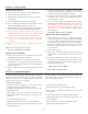
Section 1 - Quick Set-Up 5. Use the up and down arrows to change the Group number to match the Group number displayed on the receiver. Press SET and the Channel Number will flash. Quick Set-up: Receiver 1. Do not connect the receiver to any other equipment yet! 2. Connect the two antennas to the receiver. 6. Use the up and down arrow buttons to change the Channel to match the receiver. Press Set and nothing will be flashing. The channel is now set. 3.
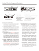
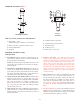
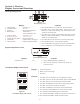
Section 3 - Detailed Components Description RE-2 Receiver Controls, Connectors, and Indicators 1 2 8 3 5 Balanced Audio power R 2 set GPA CH 12u 05 EV AU DIO -20 -10 -6 - 3 0 +3 U.S. Patent No. 6,256,484 12-15V AC/DC + 1 3 10 30 100 RE-2 BAND B Antenna Tested to Comply with FCC Standards Mic Line Line Level High Z CANADA XXXXXX S.N. 8A Telex Communications, Inc. Made in U.S.A. 3 4 Figure 1 - RE-2 Front Panel 90 Balanced Audio U.S. Patent No.
NOTE: Groups x,x,x, and x are set up to work with the other US frequency band (A and B). These groups are listed last no matter how many open channels are available. If you are using a mix of Band A and Band B, scroll down to these groups and use the clearest group. Now refer ahead to transmitter setup and return to step 9 when that is completed. 9. With the transmitter on, speak into the microphone or play the guitar.
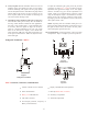
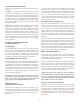
Handheld Transmitter HTU-2 2 1 3 5 7 6 SET 4 2 1 755050 8 3 9 Figure 3 Handheld Transmitter Figure 4 Transmiter HTU-2 Controls, Connectors, and Indicators 1. Main Display - LCD (Channel, Frequency or Battery Level Indication) 5. Channel/Frequency Up Switch 2. Battery Low LED - Lights when battery is low 7. Microphone Gain 3. Power On/Off Switch 8. 9V Battery Holder 4. Set Switch 9. Battery Cover - Screw type. 6. Channel/Frequency Down Switch Handheld Transmitter Setup and Operation 5.
To adjust the transmitter gain, gently insert the provided screwdriver (or other 3/32 - 2.5 mm screwdriver) into the adjustment hole opposite the display screen. Turn lightly until the screwdriver tip goes into the adjustment level control. Gently turn counterclockwise until the control stops (the microphone output is at minimum but not off). Slowly turn the gain control up (clockwise) while speaking/singing into the microphone and the audio meter shows peaks around -3 dB. 8. Verify reception.
Bodypack Transmitter Setup and Operation Have the speaker or singer use the microphone in a normal performance level voice. The Audio Meter in the main receiver display screen should show peaks around the -3 dB level. If the meter peaks all the way to the right or well below the -3 dB level, adjust the transmitter audio gain. 1. Insert Battery. Pinch the battery door tabs inward and pull the door open. Insert a 9V battery as indicated by the +/- in the holder. 2.
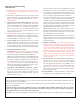
Section 4 - Receiver Display Screens and Functions 4 Main Operating Screen 2 -20 -10 -5 0 +3 CLEARSCAN T M RF 8 1 3 10 30 100 9 6 Figure 8 Main Operating Screen Display: 5. 6. 7. 8. 9. 5 AF 1 3 1. 2. 3. 4.
Transmitter On/Off Lock-Out There are two On/Off lockout modes available, One Time and Everytime. Once the working Group has been established, leave the first transmitter on, set the next receiver Group to the working Group and run ClearScanTM Group. This will provide the next clearest channel in that group. Set the transmitter to match, leave it on and repeat until all the systems are set up.
Section 5 - Trouble Shooting Guide Problem Possible Causes Solutions No audio and no display on the receiver Receiver is off Make sure that the power supply is properly connected and the on/off button is in the on position No audio and no RF signal indicator on the receiver display Transmitter is off Turn on transmitter power switch Transmitter is on a different channel Match the transmitter group and channel to the one displayed on the receiver.
Trouble Shooting Guide (continued) Possible Causes Solutions Receiver is too close to digital signal processor or similar device Move the re ceiver to a dif fer ent location Strong elec tro mag netic field from stage lighting or other source near the transmitter or receiver, which may be producing RF noise at or near the operating frequency Use ClearScanTM to change the operating frequency. Repair or remove the source of interference. Move the receiver to a different location.
Section 6 - Technical Specifications RE-2 Receiver Specifications Overall Receiver Type . . . . . . . . . . . . . . . . . . . . . . . . . . . . . . . . . . . . . . . . . . . . . . . . . . . . . . . . . . . . . . . Synthesized PLL Frequency Range (RF) . . . . . . . . . . . . . . . . . . . . . . . . . . . . . . . . . . . . . . . . . . . . . . . . . . . A Band 650 - 674 MHz B Band 698 - 722 MHz Number of Channels. . . . . . . . . . . . . . . . . . . . . . . . . . . . . . . . . . . . . . . . . . . . . . . . . .
Section 7 - Accessories and Parts MODEL No. Order No.
Section 8 - Factory Service/Warranty (Limited) FACTORY SERVICE (North America) If factory service is required, ship the unit prepaid in its original carton to:: EV Audio Service c/o TELEX COMMUNICATIONS, 8601 East Cornhusker Highway, Lincoln, Nebraska 68507-9702 U.S.A. Phone: (402) 467-5321 or 800-553-5992 Fax: 402-467-3279 Enclose a note describing the problem along with any other pertinent information and how to contact you.
TELEX COMMUNICATIONS, INC. • 12000 Portland Ave. South, Burnsville, MN 55337. PN July 2003 Made in U.S.A.