
User Manual


BTR-30N, TR-30N, TR-32N Introduction 15
.
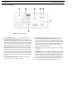
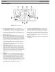
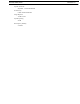
FIGURE 5. TR-30N Rear Panel/Connector/Antennas
1. MENU and SET buttons- Use to select menus and set
options on the LCD.
2. LCD (Liquid Crystal Display)
3. UP and DOWN buttons - Use to select beltpack options
on the LCD.
4. Programming Connector - Use to update software in unit.
5. Headset Connector - Male XLR or female XLR connector.
A dynamic or electret headset microphone is automatically
detected by the beltpack and a bias voltage supplied, if
needed.
6. Battery Latch - Press down to release the battery pack.
While holding the latch down, slide the battery pack about
1/8 inch back toward the latch until it stops, then lift it out.
7. Receive Antenna - Screw type 1/4-wave replaceable
antenna. The color dot on the screw end of the antenna must
match color dot on the antenna receptacle.
8. Transmit Antenna - Screw type rubber duck replaceable
antenna. Color bands near the screw end of the antenna
must match color dot on antenna receptacle.
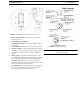
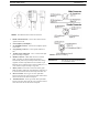
FIGURE 6. Headset Jack Wiring
IMPORTANT: Microphone gain and transmit mode is
set via software menus.