
User Manual

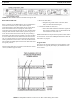
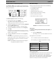

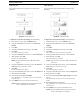
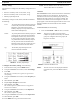

FIGURE 32. BTR-30N Base Station Link Jack and Program Jack
30 Operation BTR-30N, TR-30N, TR-32N
Base Station Link Jack
WTA 1 and WTA 2 in the BTR-30N are two (2) independent 2-
wire intercom channels. Up to 16 base stations may be
connected together to share WTA audio. Do not confuse WTA
audio with CAN bus data, as only eight (8) bases may be
connected to share CAN bus data. Not only does the WTA Link
cable pass both channels of WTA audio, it passes a logic level
so the 1st base station in the chain is the only one providing a
termination of the WTA intercom channels. Care must be taken
to connect cables between base stations from the OUT of base
one (1) to the IN of base two (2) and so forth. If the WTA link
cable is passed from OUT to OUT or IN to IN, the WTA audio
may terminate in multiple places and cause the WTA audio level
to be greatly reduced.
The base station link jacks can interface with other base stations
via two (2) different types of cables:
• Base Link Cable (BLC)
– Straight through cable. Passes CAN data, WTA
audio, and WTA termination signal.
• CAN Bus Termination Cable (CTC)
– Passes WTA audio and WTA termination signal, but
does not pass CAN data. Acts as a termination of the
CAN networks on either side of it.
Detailed information on the pinout and operation of these cables
can
be found in “Connection of Multiple Base Stations with the
Link Cables” on page 40.
Program Jack
This jack is only used for updating the internal software of the
base station. It is typically used only by the manufacturer and
service centers.
FIGURE 33. Multiple Base Stations Connected via 2-Wire Cables Sharing WTA Audio