
User Manual


10 Introduction BTR-30N, TR-30N, TR-32N
Controls and Connections
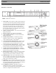
BTR-30N – Front Panel
FIGURE 1. BTR-30N - Front Panel
1. Power Switch - Do not power up a base station within three
(3) seconds of the unit being turned off. Voltages within the
unit need to drop below a threshold before being repowered.
If powered-up in less than three (3) seconds, the unit may
boot as the wrong frequency band. Even with the unit
powered down via the power switch, some circuits within
the base remain energized. To completely remove power to
the unit, disconnect the power cord.
2. [MENU] and [SET] buttons - Use to select menus and set
options on the LCD.
3. Backlit Graphics LCD (Liquid Crystal Display)
4. [UP] and [DOWN] buttons - Use to select base station
options on the LCD.
5. Portable Station Connect - Use buttons to enable or
disable the respective receiver’s audio. GREEN LED -
Audio enabled, LED OFF - Audio disabled.
6. 4-wire Selection/Peak Input Indicators - Displays when
4-wire intercoms are active with green indication. A red
indication means the intercom input level is too high.
7. 2-wire Selection/Peak Input Indicators - Displays which
2-wire intercoms are active with a green indication. A red
indication means the intercom input level is too high.
8. Auxiliary Selection/Peak Input Indicator - Displays if
auxiliary input is on with a green indicator. A red indicator
means the intercom input level is too high.
9. Headset Intercom Select - Controls the intercom to which
the local headset is connected. Each press of the button
changes the connection to channel 1, channel 2, or both.
10. Talk/Peak Light - LED is green when talk button #11 is
active. A normal mic gain setting causes the LED to flash
red on the loudest speech levels. If the gain is too high, the
LED is red at normal speech volumes.
11. Talk Button - Press to enable the audio path from the local
handset. LED #10 turns green when enabled. A quick press
and release latches button on. If the talk function is latched
on, pressing the talk button again turns it off.
12. Local Headset Connector - Male XLR connector or
female XLR connector. A dynamic electret headset
microphone is automatically detected. Microphone gain and
volume are configured in the software menus.
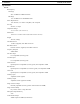
FIGURE 2. Local Headset Wiring