
User Manual


BTR-30N, TR-30N, TR-32N Operation 47
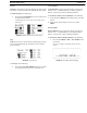
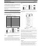
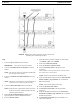
Do not set base stations to the base number 01 (Master), because
CAN bus is connected to the other base stations with a BLC, as
seen in Figure 65. If there are no masters on the CAN bus
system, there is no activity on the CAN bus line and no need for
terminations.
IMPORTANT: The master base must always
power-up after the servant bases
in order to detect servant units to control.
If all units are on a common power strip,
this is controlled by a
built in delay on the master base station.
The master base station always boots
slower than servant units.
Setup
1. Connect the power cords to the base stations.
IMPORTANT: Do not power up the base stations.
2. Connect the transmit and receive antennas to the base
stations.
NOTE: The color dots on the rear of the base should match
the color rings of the antennas.
3. Connect the main intercom audio channel(s) to the base
stations.
NOTE: This may be 2-wire intercom. This could also be 4-
wire intercom via a matrix type wired system.
4. Connect the Base Link Cable between base stations.
NOTE: Verify the OUT of the first base station connects to
the IN of second base station and follow the same
connection pattern forward.
5. Power-up all the base stations.
NOTE: The base stations should be set to all unique
transmit and receive frequencies.
6. Setup via the BTR-30N software menus the intercom, local
headset, auxiliary, stage announce, etc. as detailed in
BTR-30N Operation.
NOTE: All the base station numbers should be left as 09
(default).
7. Turn on only one (1) beltpack.
NOTE: Try to keep the beltpack at least 6’ (2 meters) away
from the base’s antennas.
8. Set the beltpack on the appropriate group and channel
for its base station.
As each beltpack is set to its group and channel, an
hourglass symbol appears on the base display in the
location normally occupied by the battery symbol. A
beltpack is assigned an ID number by the base in this time.
Finally, a normal battery symbol is displayed, indicated
the beltpack has been assigned its ID number.
9. Once the beltpack has an ID number, turn the beltpack
off.
10. Turn on the next beltpack.
11. Repeat steps 8-9 for each additional beltpack.
12. Power up the beltpacks.
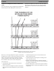
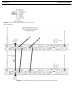
WTA and a SINGLE CAN Bus Network
These base stations connect via 2-wire and/or 4-wire audio
links and also by the Base Link Cable (BLC). The BLC cable
passes WTA audio and CAN bus data information. The CAN
bus connected base stations form a Network.
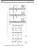
Link Overview
There are two (2) RF data communication links with a BTR-
30N system. The beltpack-to-base links convey information
such as current button(s) selected, battery level, etc. The base-
to-beltpack links convey beltpack user ID, beltpack TX
shutdown, beltpack talk shutdown, and other information.
The two (2) paths are intact when there is only one (1) base
communicating to beltpacks and when many base stations on
different TX and RX frequencies communicate to the beltpacks.
However, when one (1) or more base stations with their
transmitters off are connected to a base station with its
transmitters on, the base-to-beltpack data link is lost for those
beltpacks.
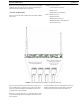
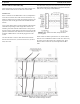
Care must be taken to connect cables between base stations
from the Out of base one (1) to the IN of base two (2) and so
forth.If the WTA link cable is passed from OUT to OUT or IN
to IN, the WTA audio terminates in multiple places and causes
the WTA levels to be greatly reduced/distorted.
IMPORTANT: The master base must always power-up
after the servant bases in order to detect
servant units to control. If all units are on
a common power strip, this is controlled
by a built in delay on the master base
station. The master base station always
boots slower than servant units.