
User Manual
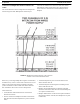
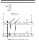
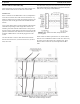

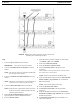

FIGURE 66. Multiple base stations connected via 2-wire audio cable
and WTA plus CAN through via BLCs
48 Operation BTR-30N, TR-30N, TR-32N
Setup
1. Connect the power cords to the base stations.
IMPORTANT: Do
not power up the base stations.
2. Connect the transmit and receive antennas to the base
stations.
NOTE: The colo
r dots on the rear of the base should match
the color rings of the antennas.
3. Connect the main intercom audio channel(s) to the base
stations.
NOTE: Thi
s may be 2-wire intercom. This could also be 4-
wire intercom via a matrix type wired system.
4. Connect the Base Link Cable between base stations.
NOTE: V
erify the OUT of the first base station connects to
the IN of second base station and follow the same
connection pattern forward.
5. Place CAN bus termination plugs (CAN-T) at the
beginning and end of the networked base stations.
6. Power-up all base stations.
7. Set all base stations to factory defaults via a four-button
reset; MENU + SET + UP + DOWN.
8. Power-down all the base stations.
9. Power-up the first
servant base station.
10. Set the servant base station to all unique receive
frequencies.
The transmitters switch off automatically
when the master
base station takes control of them.
NOTE: Leave th
e base number at the default of 09.
11. Setup via the BTR-30N software menus the intercom, local
headset, auxiliary, stage announce, etc. as detailed in
BTR-30N Operation.
NOTE: Leave the base station powered-up.
12. Power-up the master base station.
13. Set the master base station to all unique transmit
frequencies.
14. Setup via the BTR-30N software menus the intercoms,
local headset, auxiliary, stage announce, etc., as detailed
in BTR-30N Operation.
15. Set the master base station with its transmitters on to
master base number 01.