
User Manual
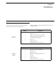
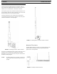
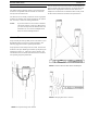
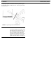


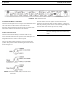
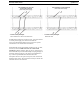
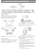

FIGURE 22. BTR-30N Rear View
28 Operation BTR-30N, TR-30N, TR-32N
4-Wire Intercom Ports
The BTR-30N can connect to two (2) 4-wire audio intercom
systems. These 8-pin modular jacks (RJ-45) are designated 4-
wire under intercom 1 and 2 titles on the rear panel. (See
Figure 22). The jack’s pinout is shown in Figure 23.
FIGURE 23. Pinout of the 4-Wire Jack
The 4-wire intercom may be used at the same time as the
2-wire intercom.
Auxiliary Input/Output
The auxiliary input jack is a combination jack. It accepts either a
3-pin XLR or a 1/4” (6.3mm) plug. The expected input is a
balanced line level input. Shown in Figure 24, the XLR plug
and 1/4” plug are wired in parallel
FIGURE 24. Auxiliary Input XLR and 6.3mm Jack Pinouts
The auxiliary output jack is a 3-pin XLR jack. It produces a line
level balanced output. Please refer to Figure 25.
The auxiliary input/output can be set to local, global, or off. (See
the Aux Settings menu in the base). The output level is
configured in the software.
• Local Aux Input - The input audio is only heard at the base
station’s local headset and beltpacks.
• Local Aux Output - The output audio is only heard at the
base station’s local headset and beltpacks.
• Global Aux Input - The input audio is heard at the base
station’s local headset and beltpacks and is placed on the 2-
wire/4-wire intercom.
• Global Aux Output - The output audio is heard at the base
station’s local headset and beltpacks and is placed on the 2-
wire/4-wire intercom.
• Off - the auxiliary input and output is off.
FIGURE 25. Pinout of the Auxiliary Output Jack