
User Manual

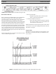


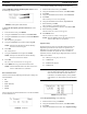
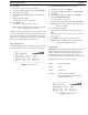


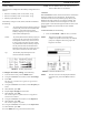

FIGURE 26. BTR-30N Rear View
BTR-30N, TR-30N, TR-32N Operation 29
Base Station Link
This pair of RJ-45 jacks allow the passage of WTA, WTA
termination control voltage, and CAN bus data between
multiple base stations. Up to eight (8) base stations may be
connected with the base station link. If just using WTA between
bases, up to 16 base stations can be connected together. The
pinout of the IN jack and OUT jack may be seen in Figure 27
and Figure 28
FIGURE 27. Base Station Link IN RJ-45 Jack Pinout
FIGURE 28. Base Station Link OUT RJ-45 Jack Pinout
Stage Announce (SA)/Relay
The Stage Announce 3-pin XLR connector (see Figure 26) is
where audio exits the base when a beltpack user pres
ses the SA
button. The pinout of the plug connector is shown in Figure 29.
FIGURE 29. Stage Announce Pinouts
FIGURE 30. Relay Output Schematic (Normally Open)
The stage announce output is balanced audio at line level. The
output level is configured in the software.
A relay contact closure also activates when a beltpack user
presses the SA button. The contacts are normally open (N.O.).
The relay schematic is shown in Figure 30. The rating of the
relay is 1 Amp at 24 volts AC or DC maximum.
A Ph
oenix type connector (supplied) plugs into the relay
contact port on the rear of the base station. This connector
provides a screw-type closure for an easy connection to wires.
See Figure 31.
FIGURE 31. Screw Terminal Adapter