
User Manual

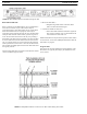


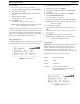


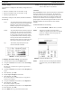

FIGURE 34. BTR-30N - Front Panel
BTR-30N, TR-30N, TR-32N Operation 31
Powering the Base Station
The base station may be powered two (2) different ways:
• Line power at the IEC receptacle. Accepts 100–240VAC, 1A
max., 50 or 60Hz.
• 24 VDC Power. Accepts a 5.5mm by 2.5mm screw on plug.
Source must supply at least 2.5 Amps.
To power on
the base station, do the following:
> Press the POWER button located on the far left of the
base station front panel.
To power
off the base station, do the following:
> Press and hold the POWER button.
Both line power and DC power can connect to the base station at
the same time. If AC line voltage drops, the base draws power
from the DC input automatically. When the AC line power is
restored, the base automatically switches back to AC power.
There is no interruption in the base operation during these
transitions.
CAUTION: Do not power up a base station within three (3)
seconds of the unit being turned off. Voltages
within the unit need time to drop below a
threshold. If powered up within the above time, the
unit may boot as the wrong frequency band.
WARNING: Even with the unit powered down via the
power switch, some circuits within the base
remain energized. To completely remove
power to the unit, disconnect the power cord.
Start Up Screen
When the BTR-30N powers up, the first screen displayed is the
Start Up splash screen. It displays for about three (3) seconds.
This screen contains both the software version number and band
ID of the base. Figure 35 shows a screen indicating software
version sb2145L and a F10 band unit.
FIGURE 35. Start Up Screen
After three (3) seconds the status screen appears.
NOTE: A
complete screen flowchart of the base station is
available in Additional Resources.
Status Screen
The Status screen is the main information screen of the base
station. It displays a number of system items:
• Frequency Group
• Band of Base Station
• Mode of Base Station
• Transmitter 1 Power Setting
• Transmitter 2 Power Setting
• Beltpack Current Activity
• Battery Life
• Base Receiver Status
FIGURE 36. Status Screen