
User Manual

BTR-30N, TR-30N, TR-32N Operation 49
16. Cycle the power of the master base while leaving the
single servant base powered-up.
The master base, on boot, takes control of the servant base
and
assign it the base ID of 02 and turn its transmitters off.
17. If there are additional servant base stations to configure,
turn off the master base station.
18. Power-up the next servant base station.
19. Repeat steps 10-12 and 16-18 for each additional servant
base.
NOTE:
• Always leave the previously assigned servant base
stations powered-up when going on to the next
base.
• The master base must always power up after the
servant bases in order to detect servant units to
control.
• If all the units are on a common power strip, this is
controlled by a built in delay in the master station.
The master station always boots slower than servant
units.
20. Repeat steps 9-19 for each additional network.
21. Turn on only one (1) beltpack.
NOTE: T
ry to keep the beltpack at least 6’ (2 meters) away
from the base’s antennas.
22. Set the beltpack on the appropriate group and channel for
its base station.
As each beltpack is set to its group and channel, an
hou
rglass symbol appears on the base display in the
location normally occupied by the battery symbol. A
beltpack is assigned an ID number by the base in this time.
Finally, a normal battery symbol displays, indicating the
beltpack has been assigned its ID number.
23. Once the beltpack has an ID number, turn the beltpack off.
24. Turn on the next beltpack.
25. Repeat steps 22-23 for each additional beltpack.
26. Power up the beltpacks.
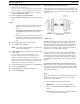
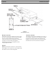
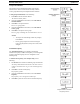
WTA and Several CAN Bus Networks
These base stations may be connected via 2-wire and/or 4-wire
audio links. They are also connected together via the Base Link
Cable (BLC) and a new cable called the CAN Bus Termination
Cable (CTC).
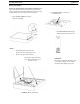
FIGURE 67. CAN Bus Termination Cable (CTC).
(Not Supplied)
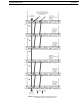
Link Overview
Multiple masters on the same C
AN bus are not allowed. The
two different cables solve this issue. The BLC passes WTA
audio and CAN bus data information. The CTC passes WTA
audio and also functions to terminate the CAN network on
either side of it. This allows many separate CAN networks to
share the same two (2) WTA audio channels.
Care must be taken to connect cables between base stations
from
the OUT of base one (1) to the IN of base two (2) and so
forth, unit to unit. If the WTA link cable passes from OUT to
OUT or IN to IN, the WTA link cable terminates in multiple
places and cause the WTA audio levels to be greatly reduced/
distorted.
The master base must always power-up after the servant
bases in order to detect servant units to control. If all units are
on a common power strip, this is controlled by a built in delay
in the master base station. The master base station always boots
slower than servant units.
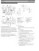
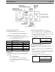
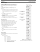
Setup
Setup is the same as the previous “WTA and a SINGLE CAN
Bus Netw
ork” section, with the exception of a CTC cable
between the two CAN networks.
1. Connect the power cords to the base stations.
IMPORTANT: Do
not power up the base stations.
2. Connect the transmit and receive antennas to the base
stations.
NOTE: The col
or dots on the rear of the base should match
the color rings of the antennas.