
User Manual

50 Operation BTR-30N, TR-30N, TR-32N
3. Connect the main intercom audio channel(s) to the base
stations.
NOTE:
• This may be 2-wire intercom. This could also be 4-
wire intercom via a matrix type wired system.
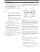
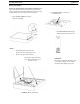
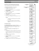
• If using a party line to connect audio channels, the
party line needs to be terminated by a connected
PSU or a load XLR plug (P.N. TP-3 or TP-3R). See
Figure 68.
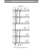
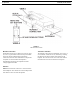
4. Connect the (BLC) Base Link Cable between base
stations within a CAN network.
NOTE: Verify the OUT of the first base station connects to
the IN of second base station and follow the same
connection pattern forward.
5. Connect the CAN Bus Termination Cable (CTC)
BETWEEN the CAN networks.
NOTE: Remember to connect from the OUT of the base
station to the IN of the next base station.
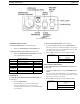
6. Place CAN bus termination plugs (CAN-T) at the
beginning and end of the networked base stations.
7. Power-up all base stations.
8. Set all base stations to factory defaults via a four-button
reset; MENU + SET + UP + DOWN.
9. Power-down all the base stations.
10. For the first network of base stations, power-up the first
servant base station.
11. Set the servant base station to all unique frequencies. The
transmitters switches OFF automatically when the master
base takes control of them.
NOTE: Leave the base number at the default of 09.
12. Setup via the BTR-30N software menus the intercoms,
local headset, auxiliary, stage announce, etc., as detailed
in BTR-30N Operation.
NOTE: Leave the servant base station powered-up.
13. Power-up the master base station.
14. Set the master base station to all unique transmit and
receive frequencies.
15. Setup via the BTR-30N software menus the intercoms,
local headset, auxiliary, stage announce, etc., as detailed
in BTR-30N Operation.
16. Set the master base station with its transmitters on to the
master base number 01.
17. Cycle the power of the master base, while leaving the
single servant base powered-up.
The master base, on boot, takes control of the servant base
and assign it the base ID of 02 and turn its transmitters off.
18. If there are additional servant base stations to configure,
turn off the master base station.
19. Power-up the next servant base station.
20. Repeat steps 11-13 and 17-18 for each additional servant
base.
Always leave the previously assigned servant base stations
powered-up when going on to the next base.
IMPORTANT: The master base must always power-up
after the servant bases in order to detect
servant units to control. If all units are on
a common power strip, this is controlled
by a built in delay in the master base
station. The master base station always
boots slower than servant units.
21. Repeat steps 10-20 for each additional network.
22. Turn on only one (1) beltpack on the
first network
system.
Try to keep the beltpack at least 6’ (2 meters) away from
the base’s antennas.
23. Set the beltpack on the appropriate group and channel for
its base station.
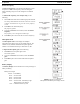
As each beltpack is set to its group and channel, an
hourglass symbol appears on the base display in the
location normally occupied by the battery symbol. A
beltpack is assigned an ID number by the base in this time.
Finally, a normal battery symbol displays, indicating the
beltpack has been assigned its ID number.
24. Once this first beltpack has an ID number, turn off the
beltpack.
25. Turn on the next beltpack.
26. Repeat steps 23-24 for each additional beltpack.
27. Power up the beltpacks.