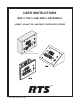
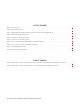
USER INSTRUCTIONS BKP-4, TKP-4, AND WKP-4 KEYPANELS ADAM™, ADAM™ CS, AND ZEUS™ INTERCOM SYSTEMS Mic t se ad He g in ait ll W Ca py Co t se ad He ar Cle e lum Vo ten Lis lk Ta WKP-4 (Mounting box optional) ™ 9350-7646-000 Rev E, 8/00
PROPRIETARY NOTICE CUSTOMER SUPPORT The RTS product information and design disclosed herein were originated by and are the property of Telex Communications, Inc. Telex reserves all patent, proprietary design, manufacturing, reproduction, use and sales rights thereto, and to any article disclosed therein, except to the extent rights are expressly granted to others. Technical questions should be directed to: COPYRIGHT NOTICE Copyright 1999 by Telex Communications, Inc. All rights reserved.
End-User License Agreement for Telex® Software IMPORTANT - Please read this document carefully before using this product. THIS DOCUMENT STATES THE TERMS AND CONDITIONS UPON WHICH TELEX COMMUNICATIONS, INC. (the “COMPANY”) OFFERS TO LICENSE THE INSTALLED SOFTWARE OR PROGRAM (“the SOFTWARE”) FOR USE WITH THE PRODUCT IN WHICH IT WAS INSTALLED. YOU ARE AGREEING TO BECOME BOUND BY THE TERMS OF THIS AGREEMENT. IF YOU DO NOT AGREE TO THE TERMS OF THIS AGREEMENT, DO NOT USE THIS PRODUCT.
This page intentionally left blank.
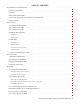
TABLE OF CONTENTS DESCRIPTION AND SPECIFICATIONS · · · · · · · · · · · · · · · · · · · · · · · · · · · · · · · · · · · · · · · · · · · · · · · · · · · 7 GENERAL DESCRIPTION . . . . . . . . . . . . . . . . . . . . . . . . . . . . . . . . . . . . . . . . . . . . . . . . . . . . . . . . 7 FEATURES. . . . . . . . . . . . . . . . . . . . . . . . . . . . . . . . . . . . . . . . . . . . . . . . . . . . . . . . . . . . . . . . . 7 FRONT PANEL DESCRIPTION . . . . . . . . . . . . . . . . . . . . . . . . . . . . . . .
LIST OF FIGURES Figure 1. Front Panel View. · · · · · · · · · · · · · · · · · · · · · · · · · · · · · · · · · · · · · · · · · · · · · · · · · · · · · · · · · · 7 Figure 2. BKP-4 Back Panel View. · · · · · · · · · · · · · · · · · · · · · · · · · · · · · · · · · · · · · · · · · · · · · · · · · · · · · · · 8 Figure 3. WKP-4/TKP-4 Configuration Switches and Connectors on Circuit Board (WKP-4 Shown) · · · · · · · · · · · · · · · · · · · · · 8 Figure 4.
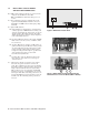
1 DESCRIPTION AND SPECIFICATIONS 1.1 GENERAL DESCRIPTION The BKP-4. TKP-4, and WKP-4 are ideal for users who want full access to the most commonly used keypanel features, and who generally communicate with four or less locations in the intercom system at any given time. The BKP-4 is suitable for desktop use and is powered from an AC mains outlet. The TKP-4 is designed to fit in a Tektronics equipment bay. The WKP-4 is designed for wall mounting.
BACK PANEL / CIRCUIT BOARD SWITCHES AND CONNECTORS Incoming Call Timeout Select: Incoming call LED flash can be set for 15 seconds, or until the caller's key is released. ■ Speaker / Microphone Selection: A DIP switch, together with the front panel Headset switch, permits any of the following speaker / microphone combinations: internal speaker with panel microphone; headphones with panel microphone; speaker with 4-pin dynamic microphone; headset with boom-mounted dynamic mic.
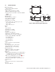
1.5 SPECIFICATIONS Matrix Input/ Output 8 dBu nominal, 20 dBu maximum Audio Performance SNR at 8 dBu (A-weighted): > 70 dB THD+N at 8 dBu (Unweighted): < 0.5% Frequency Response at 8 dBu: ± 1.5 dB from 100 Hz 20 kHz CMRR: > 70 dB Panel Mic Input Mic Type: Electret condenser Power: Phantom (+5V DC) Nominal Level: -42 dBu Maximum Level: -25 dBu Connector Type: 1/4", 3-conductor phone jack.
☞ If you are not using conduit to route the cables, use a 2 INSTALLATION 2.1 UNPACKING AND INSPECTION As soon as possible after receipt, inspect the container and contents for physical damage that may have occurred in shipping. If damage has occurred, immediately (within 24 hours of receipt of equipment) contact the carrier involved and file a claim. Save all packing materials, and request an immediate inspection by the carrier’s insurance claims agent.
Closed: keypanel cannot answer incoming calls to TIF-951. Description: The keypanel can answer incoming telephone calls received by an RTS Model TIF-951 Telephone Interface. However, it cannot perform any other telephone operations. For example, it cannot force the TIF-951 to hang up at the end of a call. In many cases, the TIF-951 can detect a hang up at the far end of the line and then hang up itself. However, this may not always be the case in all phone systems.
• ADAM CS frame with 50-pin Telco back panel: You can determine the keypanel address from the worksheet in either of two ways: 1) If you know the port number that a keypanel will be connected to, look up the port number in the worksheet, then read across to the appropriate logical keypanel number for that port number. Use that number to set the keypanel Address switch.
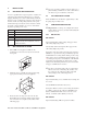
DE-9P (MALE) TO KEYPANEL 1 DE-9S (FEMALE) TO INTERCOM SYSTEM* + - 1 + - 4 AUDIO TO MATRIX + 7 AUDIO FROM MATRIX DATA 2 6 4 5 9 7 8 3 2 6 5 9 8 3 CABLE TYPE: BELDEN 8777 * IMPORTANT! When connecting to an ADAM CS back panel, use only low-profile cable connectors such as AMP Part No. 747516-3 (Telex Part No. 59926-678) Figure 6. 9-pin Intercom cable wiring diagram. Important: Shield connections at keypanel end are optional and may cause ground loops if used. Figure 8.
3 KEYPANEL SETUP 3.1 ASSIGNING INTERCOM KEYS 4) You can go through the names in the selected scroll lists by tapping the Scroll Up or Scroll Down button. 5) Tap the CWW key up to return to normal operation. You can assign keypanel intercom keys using ZEUSedit or ADAMedit. For help with key assignment in ZEUSedit or ADAMedit, click the KP button on the program's toolbar, then press the F1 key on the computer keyboard for help.
3. Press and hold the Copy button, then tap the intercom key that you want to clear. Tap up to clear the listen assignment. Tap down to clear the talk assignment. The talk or listen LED will flash to confirm that the key assignment is cleared. You can tap several keys in succession to clear them while continuing to hold down the Copy button. 4 OPERATION 4.1 HEADSET BUTTON OPERATION Operation of the Headset button depends on the position of DIP switch 4 on the back panel (page 11): 4.1.1 3.
4.2.2 Intercom Key Operation for Different Types of Key Assignments 4.2.3 Intercom Key Indications Talk Indicator: Basic Talk and/or Listen Key Operation: The down position activates talk (if assigned). The up position activates listen (if assigned). Talk and listen may be latched on or off independently by tapping up or down. ☞ The following paragraphs describe special types of key assignments called special functions.
3. 4.4 Continue talking to callers and clearing their names until the call waiting window displays dashes (no callers). Also, when all calls have been answered, the green LED next to the call waiting key will turn off. OPERATION WITH THE TIF-951 TELEPHONE INTERFACE If DIP switch 3 (page 10) is set to the Open position, you can use the keypanel to answer incoming telephone calls that have been received by the TIF-951.
Table 1.
Table 2.