User Instructions Model EMS-4001 Expansion Master Station Audiocom® Intercom Systems 9350-7713-000 Rev.
FCC Statement This equipment uses, and can radiate radio frequency energy that may cause interference to radio communications if not installed in accordance with this manual. The equipment has been tested and found to comply with the limits of a Class A computing device pursuant to Subpart J, Part 15 of FCC Rules which are designed to provide reasonable protection against such interference when operated in a commercial environment.
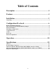
Table of Contents Description ................................................................................ 4 Features ..................................................................................... 4 Installation ................................................................................. 5 Unpacking ..................................................................................................................................... 5 Configuration Pre-check ..................................
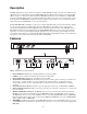
Description The EMS-4001 adds four powered intercom channels to an MS-2001 Master Station, and it provides talk, listen and call buttons for the added channels. Up to four EMS-4001 Expansion Master Stations may be connected to the MS2001 to add up to 16 channels (18 channels total). The MS-2001 microphone is used to talkback to the EMS-4001 channels, and the MS-2001 speaker is typically used for listening.
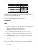
9. Program Inputs Connector and Trimmers: Each intercom channel has its own program input and level adjust trimmer. For each program input, there is an internal jumper which routes the program either to the intercom channel only, or to both the intercom channel and the MS-2001 headset or speaker (default setting). Additionally, the program signal to the intercom channel may be turned on or off via the MS-2001 front panel programming.
WARNING The following instructions are for use by qualified personnel only. To avoid electric shock, do not remove the cover unless you are qualified to do so. AVERTISSMENT Les instructions qui suivent s’adressent uniquement a un technicien qualifie. Pour evite des chocs electriques, ne pas ouvrir le boitier, a moins d’y habilite. Configuration Pre-check Before making connections, read the configuration notes that follow, and make sure that all switches and jumpers are properly set for your intended usage.
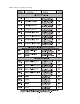
Table 1 - EMS-4001 configuration switch settings.
Table 2 - EMS-4001 jumper settings. Mounting Configurations The EMS-4001 mounts in a standard 19 inch equipment rack and is 1 rack unit high. Install the two supplied rack mount cosmetic covers when installing the EMS-4001 in the rack. When rack mounting components, you may not be able to access the sidetone trimmers after the components have been mounted. In this case, you can position the components in the rack and make all required connections.
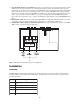
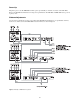
Power-Up Plug in the power cord. The EMS-4001 channels power-up identically to channels one and two of the MS-2001. Refer to the MS-2001 User Instructions for all power-up information. The MS-2001 and EMS-4001 can be powered up in any order. Sidetone Adjustments Use the sidetone adjustment procedure as described in the MS-2001 User Instructions, except substitute channel 3, channel 4, etc. The locations of the EMS-4001 sidetone trimmers are shown in Figure 4. Figure 3 - Example of EMS-4001 in a system.
Figure 4 - EMS-4001 sidetone adjustment locations. Operation The EMS-4001 channels operate identically to channels one and two of the MS-2001. Refer to the MS-2001 User Instructions for all operating information. Specifications General Input and Output Power: AC Input: 100-240 VAC, 50/60 Hz Channel Power (each channel): 24 ±1 VDC, 2 A Dimensions: 1.75” (44.5 mm) high, 19” (483 mm) wide, 10.31” (261.9 mm) deep Weight: approximately 4.
Call Signaling: Send: 20 kHz ±100 Hz, 0.5 Vrms ±10% Receive: 20 kHz ±800Hz, 100 mVrms Mic-Kill Frequency: Send: 24 kHz ±100 Hz, 0.