ICW-3 Window Intercom Installation and Operation Instructions 9350-7686-000 Rev L 8/2006
PROPRIETARY NOTICE SHIPPING TO THE MANUFACTURER The product information and design disclosed herein were originated by and are the property of Telex Communications, Inc. Telex reserves all patent, proprietary design, manufacturing, reproduction, use and sales rights thereto, and to any article disclosed therein, except to the extent rights are expressly granted to others. All shipments of product should be made via UPS Ground, prepaid (you may request from Factory Service a different shipment method).
Unpacking and Inspection Unpacking and Inspection ICW-3 Package 1. IEC Cord 2. Switching Power Supply 3. ICW-3 to power supply cord 4. #6 screws 1” (3). 5. Adjustment screwdriver 6. Customer Assembly 7. Operator Assembly FIGURE 1. ICW-3 System Components Unpack the equipment from the shipping case and inspect for missing or damaged components. You should have all of the items listed in Figure 1 . Recommended Items 1. No.1 Phillips screwdriver 2.
Specifications General Power Requirement 12 to 15 VDC, 150 mA nominal System Frequency Response 200 to 4.5 kHz ±3 dB Environmental -20° C to 55° C, 0% to 90% humidity, non-condensing Outputs External Speaker 2W: 100dB SPL at 1ft. at 1 kHz, C weighting Internal Speaker 2W: 100dB SPL at 1ft. at 1 kHz, C weighting Note: These are sine wave maximums. Voice measurements will range 70 to 90 dB SPL.
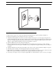
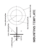
Installation FIGURE 2. ICW-3 Assembly Detail Installation 1. Remove the two screws (one on each side) holding the mounting plate to the operator assembly. (See Figure 2 .) 2. Measure and identify the location where the intercom is to be mounted. 3. Attach the mounting template to the window (customer assembly side) being sure to center the appropriate guide in the location identified in step 2. Note, there are two guides provided on the last page of these instructions.
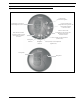
FIGURE 3. Operator and Customer assemblies Connecting customer and operator assemblies prior to final mounting. FIGURE 6. Vox Circuit Adjustment FIGURE 4. FIGURE 5. 6 Mounting Template Customer Side Mounted NOTE: The unit is shipped from the factory with the VOX circuit pre-adjusted. Use this procedure only if you encounter a problem where the VOX circuit does not properly switch between the operator and customer when they are talking.
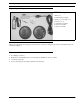
Operation Operation Connection for gooseneck microphone Loudspeaker is interrupted when headphones are in use Controls volume of the loudspeaker on the operator side. Rotate knob clockwise to increase volume Controls volume of the loudspeaker on the customer side. Rotate knob clockwise to increase volume When the MUTE button is pushed in, both the inside and outside microphones are muted.