User Instructions Model SS-1002 Single Channel Intercom Speaker Station Model SS-2002 Two Channel Intercom Speaker Station Model SS-2002RM Two Channel Rack Mount Intercom Speaker Station Audiocom® Intercom Systems 9350-7741-000 Rev A, 10/2002 1
FCC Statement This equipment uses, and can radiate radio frequency energy that may cause interference to radio communications if not installed in accordance with this manual. The equipment has been tested and found to comply with the limits of a Class A computing device pursuant to Subpart J, Part 15 of FCC Rules which are designed to provide reasonable protection against such interference when operated in a commercial environment.
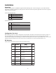
Table of Contents Introduction............................................................................... 4 Description ................................................................................ 4 Features ..................................................................................... 4 Installation ................................................................................. 6 Unpacking .....................................................................................................
Introduction Thank you for purchasing the Audiocom SS-1002/SS-2002/SS-2002RM Intercom Speaker Station. We hope the many design features of this product will satisfy your intercommunication requirements for many years to come. To get the most out of your new intercom station, please take a few moments to look through this booklet before using the Intercom Speaker Station for the first time.
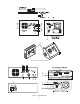
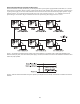
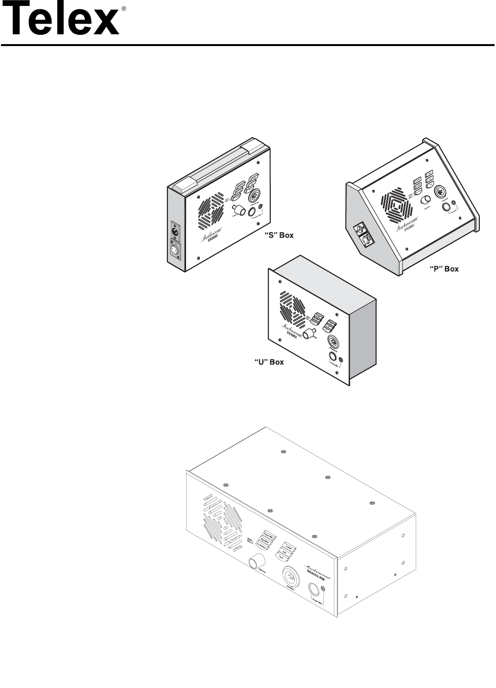
Figure 1 - SS-1002 / SS-2002 features. Figure 2 - SS-2002RM features.
Installation Unpacking Each SS-1002 / SS-2002 / SS-2002RM is supplied with the following items. Contact the shipper or your Audiocom dealer immediately if anything is damaged or missing. Be sure to fill out and return the product registration card to Telex to properly register your intercom station.
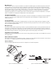
Mic Kill Receive Audiocom master stations, such as the US-2002A, can transmit an inaudible signal to turn off the microphones in all remote intercom stations on an intercom channel. This is useful when a remote intercom station has been left unattended with the microphone on. The procedure to send a mic kill signal from a master station is a two-step process, so that it is very unlikely that microphones will ever be turned off by accident.
Headset Connector Notes If you are using a monaural, dynamic-mic headset, or a monaural, telephone-style, dynamic-mic handset, or a handheld dynamic microphone, plug it into the Headset connector. You can also use this connector with monaural headphones for listening when you are using either the built in panel microphone, or the optional gooseneck microphone for talk back.
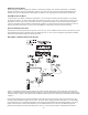
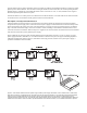
intercom stations may be reduced. Generally, if intercom stations are within a few hundred feet from the system power supply, phantom power will be sufficient. Also note that increasing the number of stations will reduce the overall operating distance. Phantom power is generally the only method that will be used to connect the “S” box, “P” box, and RM versions. Figure 5 illustrates a phantom powered intercom system.
All Locally Powered Intercom Stations (Dry Lines) If intercom stations are widely distributed, you can dispense with a system power supply (PS2001L, SPS-2001, etc.) and use local power for each station. When no power is delivered on the intercom channels, this is known as dry-line operation. Since a system power supply is not used, a line termination must be inserted in each intercom channel for proper operation. Again, note that only the “U” box has provisions for local power.
Figure 9 - Audiocom mode connections for an SS1002 Intercom Station in a “U” box. Note: for Clear-Com connection, use the Unbalanced Mode Intercom Channel pin-out information listed in the Specifications section.
Figure 10 - Audiocom mode connections for an SS2002 Intercom Station in a “U” box. Note: for Clear-Com connection, use the Unbalanced Mode Intercom Channel pin-out information listed in the Specifications section.
Figure 11 - Audiocom cable wiring diagrams.
Power-Up Make sure any local power supplies are plugged in, then turn on the power switches of any phantom power supplies (PS2001L, SPS-2001, etc.) Sidetone Adjustment The SS-1002, SS-2002, and SS-2002RM use full-duplex audio (the same as conventional telephone lines) in which the talk and listen audio are sent and received on the same wires. Thus, when you talk, you also here your own voice back as with a telephone.
Operation Channel Select (SS-2002 & SS-2002RM Only) Tap the Ch Select key to select channel 1 or 2. The key is green when channel 1 is selected and red when channel two is selected. Headset/Headphone/Speaker/Microphone Selection • To use a headset or telephone style handset, set the Speaker and Panel Mic keys to off.
Specifications General Power Requirements: Phantom Power: +24 VDC nominal, 175 mA Local Power: +12 to +15 VDC, 250 mA Dimensions: See dimension drawings.
Call Signaling: Pin 1 - Common Pin 2 - Local power (+12 to +15 VDC) If needed Pin 3 - Power +30 VDC Pin 4 - Intercom channel 1 audio and DC call signaling Pin 5 - Power +30 VDC Pin 6 - Intercom channel 2 audio and DC call signaling Dimensions Speaker Output Power 4W max @ 8 ohms 17
TRADEMARKS Audiocom® is a registered trademark of Telex Communications. Names of other products mentioned herein are used for identification purposes only and may be trademarks and/or registered trademarks of their respective companies. WARRANTY INFORMATION Products are warranted by Telex Communications, Inc. to be free from defects in materials and workmanship for a period of one year from the date of sale.