Telex® User Instructions WM 200 TM 0 GR RE N 1 D2 Ch Se Lis ten lec t Ca ll Talk Vo lu me He ad se t WM2000 Shown Model WM1000 / WM2000 Wall Mount Intercom Stations Audiocom ® Intercom Systems ®
FCC Statement This equipment uses and can radiate radio frequency energy that may cause interference to radio communications if not installed in accordance with this manual. The equipment has been tested and found to comply with the limits of a Class A computing device pursuant to Subpart J, Part 15 of FCC Rules which are designed to provide reasonable protection against such interference when operated in a commercial environment.
Table of Contents Description . . . . . . . . . . . . . 4 Features . . . . . . . . . . . . . . 5 Installation . . . . . . . . . . . . . 6 Unpacking . . . . . . . . . . . . 6 Configuration Switch Pre-check . . . . . . . . 6 Intercom Channel Connections . . . . . . . . 7 Dynamic-Mic Headset Connection . . . . . . . 9 Power-Up . . . . . . . . . . . . 10 . . . . . . . . . . 10 . . . . . . . .
Audiocom® Description The WM1000 and WM2000 Intercom Stations are designed for stationary, wallmounted installation in standard two-gang electrical boxes. The WM1000 is a single-channel station; the WM2000 provides switch-selectable access to either of two intercom channels. The WM1000 and WM2000 are ideal when users need to access the intercom system from strategic locations where a desktop station would be unsuitable, but they do not wish to carry around a belt-pack station.
Features 1. Channel Select Switch (WM2000 Only): Used to switch between intercom channels one and two. The switch lights green for channel one and red for channel two. 2. Intercom Listen Key: Both momentary (push-to-listen) and latching (hands-free listen) are possible. 3. Call Key: Used to send call signals on the intercom channel and to indicate incoming calls. 4. Intercom Talk Key: Both momentary (push-to-talk) and latching (hands-free talk) are possible.
Audiocom® Installation Unpacking Each WM1000 / WM2000 is supplied with the following items. Contact the shipper or your Audiocom dealer immediately if anything is damaged or missing. Detach and fill out the registration card and return it to Telex to properly register your intercom station.
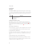
Table 1.
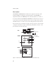
Audiocom® General Information ☞ After connecting intercom stations as described below, and before installing the mounting screws, connect a headset and perform the sidetone adjustment as described on page 10. The WM1000 and WM2000 mount in a standard two-gang electrical box. Some example intercom system configurations are shown in Figures 2 through 5, pages 12 through 14. Detailed connections for the WM1000 and WM2000 are shown in Figures 6 and 7, pages 15 and 16.
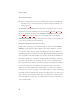
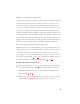
Method 2: Locally Powered Connection Using this method, the intercom station is connected to the intercom line just like any phantom-powered intercom station, except that a local power supply is also connected. This local power supply is located right with the intercom station and provides power for that station only. Since power loss on the intercom lines is no longer an issue, the operating range is now limited only by the audio transmission range, which is several miles.
Audiocom® Power-Up Make sure any local power supplies are plugged in, and turn on the power switches of any phantom power supplies. ☞ If you are using a large number of locally powered intercom stations, you should activate their local power supplies before activating any phantom power supply. Otherwise, you may get an overload indication on the phantom supply. In this case, either reset the phantom supply, or momentarily turn it off, then on.
6. Install the intercom station mounting screws after completing the adjustments. The station is now ready for use. If you are using headphones that completely enclose the ears, adjust sidetone as follows: 1. Activate channel 1 as described in the operating instructions. (Required only for the WM2000, the WM1000 is active on whichever channel it is connected to.) 2. Activate talk and listen as described in the operating instructions. 3.
Audiocom® 500 METERS Audiocom Audiocom Listen WM2000 Ch Select Volume Audiocom Listen WM2000 Call GRN 1 RED 2 Listen WM1000 Call Call GRN 1 RED 2 Talk Ch Select Volume Headset WM2000 Talk Talk Volume Headset Headset WM1000 WM2000 LOCAL POWER 12 to 15 VDC, 65 to 150 mA Audiocom Audiocom Listen WM2000 Ch Select Volume Audiocom Listen WM1000 Call GRN 1 RED 2 Listen WM2000 Call Talk Call GRN 1 RED 2 Talk Volume Headset WM2000 Ch Select Volume Headset Talk Headset
Audiocom Ch Select Audiocom Listen WM2000 GRN 1 RED 2 Volume WM2000 WM2000 Audiocom Ch Select Volume WM2000 WM2000 Audiocom Listen Audiocom Volume Volume MADE IN USA Audiocom Talk Headset Listen WM2000 Ch Select Volume Headset PS2000L Audiocom Volume Headset WM1000 WM2000 WM2000 Listen WM2000 Ch Select Volume Talk Headset MADE IN USA Headset WM2000 Audiocom CHN 2 CLASS 2 WIRING 1.
Audiocom® Audiocom Listen WM1000 Audiocom Volume Ch Select Volume WM1000 Audiocom Listen WM2000 Call GRN 1 RED 2 Headset Listen WM2000 Call Talk Call GRN 1 RED 2 Talk Ch Select Volume Headset WM2000 Talk Headset WM2000 LOCAL POWER 12 to 15 VDC, 65 to 150 mA LOCAL POWER 12 to 15 VDC, 65 to 150 mA LOCAL POWER 12 to 15 VDC, 65 to 150 mA LINE TERMINATION Audiocom Listen WM2000 Audiocom Listen WM1000 Ch Select Volume WM2000 LOCAL POWER 12 to 15 VDC, 65 to 150 mA Volume Heads
TO ADDITIONAL SINGLE-CHANNEL STATIONS TO POWER SUPPLY CONNECTOR Pair 1 Channel Audio high / Power Channel Audio low / Power Pair 2 DC Common Shield* Shield* PIN 1 OPTIONAL LOCAL POWER SOURCE 12 to 15 VDC, 65 to 150 mA + DC COMMON Cable Type: 22AWG Stranded, 2-Pair Twisted-wire, with Shield Denotes twisted pair. Denotes shield. *Shield: Earth ground (Connect at power supply only. Do not short to DC common) Figure 6.
Audiocom® TO ADDITIONAL SINGLE- OR TWO-CHANNEL STATIONS TO POWER SUPPLY CONNECTOR Channel 2 Audio low / Power Channel 2 Audio high / Power Channel 1 Audio low / Power Channel 1 Audio high / Power Pair Pair DC Common Pair Shield* Shield* PIN 1 OPTIONAL LOCAL POWER SOURCE 12 to 15 VDC, 65 to 150 mA + DC COMMON Cable Type: 22AWG Stranded, 3-Pair Twisted-wire, with Shield Denotes twisted pair. Denotes shield. *Shield: Earth ground (Connect at power supply only. Do not short to DC common) Figure 7.
Operation Channel Select (WM2000 Only) Tap the Ch Select key to select channel 1 or 2. The key is green when channel 1 is selected and red when channel two is selected. Receiving Calls 1. When there is an incoming call signal the Call key will flash red. There will also be a beep tone in the headphones if the beep feature is activated (page 6). ☞ WM2000 only: incoming call indication is provided only for the currently selected channel. 2. Turn on the Talk and Listen keys and begin your conversation.
Audiocom® Specifications General Power Requirements: Phantom Power: 24 VDC nominal (12 to 30 VDC), 65 to 150 mA Local Power: 12 to 15 VDC, 65 to 150 mA Dimensions: Mounts in standard two-gang electrical box Environmental Requirements: Storage: -20°C to 80°C; 0% to 95% humidity, non-condensing Operating: -15°C to 60°C; 0% to 95% humidity, non-condensing Dynamic-mic Headset Microphone: 50 to 200 ohm, dynamic (balanced or unbalanced) Headphones: 150 to 600 ohm, monaural Connector Type: XLR-4M Pin 1 Microphon
Intercom Channel, Unbalanced Mode (SW1 set to UNBAL position) Output Level: 1 Vrms ±10% Input Impedance: 150 ohms Bridging Impedance: greater than 10,000 ohms Call Signaling: Send: 11 ±3 VDC Receive: 4 VDC minimum Connector Type: Six-position terminal block with screw-in wire clamps Pin 1 Common Pin 2 Local power (12 to 15 VDC, 65 to 150 mA) Pin 3 Channel 1 +24 VDC input Pin 4 Channel 1 Intercom audio high and DC call Pin 5 Channel 2 +24 VDC input Pin 6 Channel 2 Intercom audio high and DC call
Audiocom® Factory Service and Parts Information When returning equipment for repair include your return address, telephone number and proof of date of purchase, along with a description of the problem.* The address for Audiocom equipment returns and parts information is: Service Department Telex Communications, Inc. West 1st Street Blue Earth, Minnesota 56013 U.S.A. Telephone: (507) 526-3205 (Collect calls not accepted) Warranty Repairs - If in warranty, no charge will be made for the repairs.
Notes 21
Audiocom® Notes 22
Notes 23
® TELEX COMMUNICATIONS, INC. 9350-7621-000 Rev. C, 10/98 9600 Aldrich Ave. So., Minneapolis, MN 55420 U.S.A.