PAM-32 User Guide Up to and including firmware version 1.1.
SHIPPING TO THE MANUFACTURER PROPRIETARY NOTICE The product information and design disclosed herein were originated by and are the property of Telex Communications, Inc. Telex reserves all patent, proprietary design, manufacturing, reproduction, use and sales rights thereto, and to any article dislcosed therein, except to the extent rights are expressly granted to others. COPYRIGHT NOTICE Copyright 2006 by Telex Communications, Inc. All rights reserved.
Table of Contents CHAPTER 1 Introduction ................................................................3 PAM-32 Production Audio Monitor ...........................3 General Description ...................................................3 Features .....................................................................3 Connections ................................................................4 Keypanel Connections ...............................................4 Specifications ..........................
2
CHAPTER 1 Introduction PAM-32 Production Audio Monitor General Description The RTS™ Model PAM-32 keypanel fits in a standard 19” rack and is two rack spaces high. It has 32 push button keys; 30 of which are monitoring inputs; one key for copying from alpha scroll lists; and one is for headset/speaker. It adds significant new features such as digital signal processing and binaural headset operation with left/right assignment of audio signals.
Introduction Connections Keypanel Connections Connections are identical for each keypanel. 1. Intercom Connection: Use a standard RJ-12 or DB-9 intercom cable (Figures 1 and 2). Connect from the FRAME connector to an available intercom port. 2. EXP Connect: 3. LCP Connect: 4. Auxiliary Input Connection: Connect an auxiliary audio input to the AUX INPUT connector on the backpanel. This is used as a second input from the matrix during split operation.
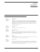
Specifications Specifications The PAM-32 is a 32-key (push button) monitor panel, with both headset and speaker outputs. General AC Supply: External, switching type, 100-240 VAC, 50/60 Hz with locking DIN connector for attachment to the keypanel and Input Nominal Environmental +8dBu Storage Peak -40°C to 60°C (-40°F to 140°F) ±20dBu max. Operating Aux Inputs (Side B) -10°C to 41°C (14°F to 105.8°F) Input Level Dimensions +8dBu nominal 19” wide x 2RU x 3.
Introduction Matrix Out Balanced Output Power Input Connector Type Type: Pin Out 5-pin locking DIN Pin 1 Shield (circuit common) Common Pin 2 Audio output + Common Pin 3 Audio output - Pin Out Pin 1 Pin 2 Pin 3 +5 VDC, 1.50A max. Pin 4 -15 VDC, 0.150A max. Pin 5 +15 VDC, 0.5A max.
CHAPTER 2 Installation Option DIP Switch Settings Switch 1: Latch Enable/Disable Default Setting: Open: Enable Description: An intercom key can always be turned ON for momentary listening by pressing and holding the key during the monitoring. There is also an electronic latching feature that lets you tap intercom keys to9 turn them ON or OFF. This permits convenient hands-free monitoring. However it can also result in a listen circuit being left ON unintentionally.
Installation Switch 6: Standard / Alternate Keypad Sequence Default Setting: Description: For Standard Keypad Sequences (DIP 6 Open) Listen Key ON - Solid Green LED Listen Key Locked ON (in “one” mode) - Solid Red LED Listen Key Held ON, doing ISO (in “many” mode) - Solid Red LED In-use Tally (e.g. IFB being interrupted) - Solid Red LED Busy Tally (e.g. no trunks available) Flashing Red LED NOTE: Tallies also tally on the alphanumeric display.
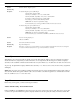
Operation method of determining the proper Address switch setting varies for each intercom system. Use the method for your intercom system as described below. Then set the white point on the Address switch to point to the correct setting. Address Setting for Zeus Intercom port connectors on the Zeus back panel are arranged in three groups of eight intercom ports. For each group, intercom port connectors are labeled ID1, ID2, etc.
Installation 10
11 1 2 3 4 5 6 7 8 201 202 203 204 205 206 207 208 401 402 403 404 405 406 407 408 601 602 603 604 605 606 607 608 1 2 3 4 5 6 7 8 1 2 3 4 5 6 7 8 1 2 3 4 5 6 7 8 1 2 3 4 5 6 7 8 Settings for ADDR 9 616 615 614 613 612 611 610 609 416 415 414 413 412 411 410 409 216 215 214 213 212 211 210 209 16 15 14 13 12 11 10 624 623 622 621 620 619 618 617 424 423 422 421 420 419 418 417 224 223 222 221
12
CHAPTER 3 Basic Operation Screen Saver Operation If the PAM-32 is set for screen saver operation, the alpha numeric display automatically shuts off after a user defined period of inactivity. The display reactivates on incoming call or when the keypanel operator actuates any control. DIP switch 3 enables and disables the screen saver operation. NOTE: You can override the normal time-out period for the screen saver operation and immediately place the keypanel in screen saver mode.
Basic Operation Intercom Keys and Displays Alphanumeric Display Indications for Intercom Keys Upper Case Letters: Upper case letters indicate keys that have an assignment. Dashes ----: Dashes indicate a key that has no talk or listen assignment. Flashing Alphanumeric Display: This means the key is activated to listen to an IFB, ISO or TIF.
CHAPTER 4 PAM-32 Menu System Menu System, Menu Access 1. Clear all names from the Call Waiting display (if not clear) by tapping one or more time on the Call waiting key. 2. Tap MENU to activate the menu system. 3. Press the ⎠⎠ to scroll forward through the list of menus. Press the −− to scroll back. 4. Tap FWD or PGM to enter a menu. Tap BACK to exit a menu. 5. Within a menu: Press ⎠⎠ or −− to scroll.
PAM-32 Menu System Display Menu, Matrix Displays the intercom system name for all talk level 1 key assignments. In non-trunked intercom systems, the intercom system name is always LOCL (local). In trunked intercom systems, intercom system names are created in AZedit. Display Menu, Panel ID Panel ID displays the calculated port number that the keypanel is connected to. The calculation is based on the data group that the keypanel is connected to, along with the Address switch setting on the keypanel.
Menu System, Key Assign Menu 6. Tap PGM or FWD to select a list. In some cases Wait may display while the requested list is uploaded from the intercom system. Tap Key should now display. 7. Tap an available intercom key to assign a listen-only key. If you assign a key that is listen only, the assignment will appear briefly in upper-case letters, then will change to lowercase letters.
PAM-32 Menu System 3. Tap PGM Tap Key displays. 4. Tap any key in the row where you want to assign the setup page. The key assignments for that page should appear in the displays. 5. You can press the ¯ ¯ or -- to select or assign another setup page. Or, tap CLR to exit. NOTE: You do not need to run Save Cfg to store changes to setup pages. These are stored in the intercom system.
Service Menu Press ⎠⎠ to select any of the following: Auto Baud: Senses what the Matrix is running, and sets the PAM accordingly. 9600 Baud 76.8 K Baud 2. NOTE: Run Service Menu, Save Cfg to store the settings. Service Menu, DSP Func This item increases the digital signal processing features. 1. Select DSP Func, then tap PGM. Filtering displays. 2. Press⎠⎠ or −− to display any of the following items: Filtering Gating Metering Mixing Metering Metering lets you use the Vol.
PAM-32 Menu System 3. Tap PGM. ♦ Mic or Mic displays. If an arrow displays, this indicates the mic signal is currently being routed to the destination that you selected in step 2 4. To toggle the selection, press PGM. You can also press ⎠⎠ or −− to display and toggle any of the following items: Mic Matrix Aux 1 Aux 2 5. Tap CLR to exit when you are finished changing the mixing selections. 6. Run Service Menu, Save Cfg to store any mixing changes.
Service Menu 1. Select Min Volume from the Service menu, then tap PGM. ♦Speaker displays. 2. Press ⎠⎠ to select either Speaker or Headset. 3. Tap PGM. 4. Press ⎠⎠ or −− to increase or decrease the minimum volume level. The range is -24dB to -60dB or full Mute. 5. Tap PGM. 6. Tap CLR to exit. 7. Run Service Menu, Save Cfg to store Min Volume settings. Service Menu, Mod Assign NOTE: Normally, this is a service adjustment that is required only when replacing a key an display module.
PAM-32 Menu System 3. Tap CLR to exit. 4. Run Service Menu, Reset Cfg to store the Output Level settings. Service Menu, Reset Cfg Reset Cfg restores all custom settings to the defaults and erases all stored autodial numbers. Service Menu, RVON Setup NOTE: To use the RVON-1 with the PAM-32, the PAM must be at firmware version 1.0.0 or higher. The RVON-1 card, when shipped has a default IP Address already configured.
Service Menu NOTE: Once you have entered the Netmask, you may need to enter the Gateway IP Address. A Gateway is a node (for example, a computer) on a network that serves as an entrance to another network. 16. Press PGM. The actual Gateway IP Address appears. 17. Enter the first number in the Gateway IP Address. This activates the first octet of the Gateway IP Address and clears the rest of the address. 18. Press PGM.
PAM-32 Menu System 8 hr 10 hr 12 hr Service Menu, Test Panel Test Panel PGM lets you check the operation of all keys and displays. All alphanumeric displays show a% symbol. Pressing down on any key (except the Headset/Vol Sel. key) will cause OK to display. This verifies operation of the key. Tapping on the Headset/Vol.Sel. key will cause the display to cycle through the available selections.