Telex Operating Instructions Telex R TM Personal Listening Systems PST-170 PST-170 17 Channel Synthesized Transmitter R
PST-170 SPECIFICATIONS Number of Channels · · · · · · · · · · · · · 17 User Selectable Channels Power Output · · · · · · · · · · · · · 80,000 uV/M at 3 meters, maximum Antenna · · · · · · · · · · · · · · · · · · · Permanently attached trailing wire Modulation · · · · · · · · · · · · · · · · · · · · · · · FM, +/- 25 KHz Deviation Frequency Response (System) · · · · · · · · · · · · 100 Hz to 10,000 Hz Audio Input: Microphone, 7.75 mV RMS input for 25 KHz deviation. Impedance, 10 K Ohms, nominal. Aux.
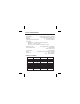
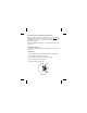
Telex R ANTENNA AUXILLIARY INPUT JACK fdffdlf; TM Personal Listening Systems PST-170 BATTERIES Side View Front View The PST-170 Transmitter uses two AA batteries. Position them in the battery compartment as illustrated. You can expect 8 hours of operation from alkaline batteries and 4 hours on nickel-cadmium batteries. Charge Pins are provided on the bottom of the unit that fit Telex drop in chargers. CAUTION: Do not attempt to recharge alkaline batteries as this may result in personal injury.
Transmitter Channel The PST-170 Transmitter may be set to any one of 17 channels. Two Transmitters cannot operate on the same channel unless separated by 300 feet (91 m) or more (which is the average maximum operating range). If two transmitters are operating on the same channel inside this perimeter, the receivers will pick up the FM signal of both transmitters, causing a squealing sound to be heard.
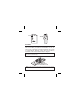
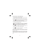
The second jack is the microphone input. This jack is located on the top panel “step” of the transmitter. The microphone is supplied with the transmitter but other types can be used as well. SET SWITCH BUTTON SWITCH BUTTON ANTENNA MICROPHONE JACK SET -dB E.D.R. OFF POWER SWITCH Top View Frequency/Channel Considerations As with any radio device, interference can occur at any time. The frequencies offered are shared with other legitimate users.
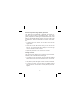
Placement of the Transmitter and Microphone Place the transmitter on the users belt or in their pocket, preferably with the antenna facing the receiver. Do not coil the antenna and put it in a pocket. This will severely reduce the operating range. Place the microphone about 10 to 12 inches below the mouth of the user. Transmitter Operation Turn on the transmitter with the toggle switch on top of the PST-170. LCD Display 1. Channel Display A through Q, low battery indicator and input level 2.
Channel Selection and Input Adjustment 1. Turn the receiver on and plug a microphone into the mic jack. A channel letter will show in the display. 2. Press the set button once and the Channel indicator will flash. 3. Press the button and the Channel will cycle up. Match the channel to the receivers being used (SR-50, SR-100, SR-400 or check frequency chart to match other brands). 4. Press SET, the channel indicator will stop flashing and the in- put level will be displayed and flash. 5.
Enhanced Dynamic Range (E.D.R.) Operation The Telex PST-170 Transmitter is equipped with E.D.R., Enhanced Dynamic Range (companded) audio. This mode greatly improves the Audio Signal to Noise Ratio when used with the Telex Model SR-400 receiver. The E.D.R. mode must be selected on both the transmitter and receiver to be effective. 1. To engage the E.D.R. function turn the PST-170 off with the toggle switch. 2. Press and hold the SET button while you turn the PST-170 back on. The E.D.
Low Battery Indication 1. When there is approximately 10% of the battery life left, a bat- tery symbol will flash alternately with the Channel letter in the LCD display. 2. When there is only 5% battery life left, the battery symbol will constantly flash in the display. System Walk Through Now that the transmitter is set up, you should be able to hear the program material on the receiver. Walk the receiver through the area that it is intended to be used in.
FCC INFORMATION The Telex Model PST-170 is authorized under FCC Rules Part 15. Licensing of Telex equipment is the user’s responsibility and licensablilty depends upon the user’s classification, and frequency selected. CAUTION: Changes or modification made by the user could void the user’s authority to operate the equipment.
WARRANTY INFORMATION FILL OUT AND RETAIN THIS PORTION FOR YOUR RECORDS Model(s) _________________________ Serial No(s).:_____________________ Date of Purchase __________________________________________________ Purchased From __________________________________________________ Address _________________________________________________________ City _______________________ State______________ Zip _______________ LIMITED WARRANTY (VALID UNITED STATES AND CANADA ONLY) TELEX Communications, Inc.
" Model No(s).:_____________________________ Serial No(s).
R TELEX COMMUNICATIONS, INC. 12000 Portland Ave. South, Burnsville, MN 55337 PN 38110370 June 2004 Made in U.S.A.