PW24-2 2.
TABLE OF CONTENTS 1. 2. 3. 4. 5. 6. 7. Revision B Quick Set Up and Operation ....................................................... 3 Installation.................................................................................... 4 Guidelines For Best Performance................................................ 5 Troubleshooting Guide................................................................. 6 Technical Specifications ..............................................................
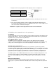
QUICK SET UP AND OPERATION Synching Up The Transmitter and Base 1) Turn the transmitter power switch to on and place the transmitter in the recharge cradle of the base. The transmitter goes in the base with the beltclip facing out. 2) The recharge LED will light (Green if fully charged, Red if charging) and the In-Use Green LED on the base and transmitter will flash 3 times.
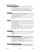
microphone starts recording at the same time. The transmitter must be turned on and in standby mode. 19) A +5V signal on the Auto Talk line means the microphone is off. 20) 0V or ground on the Auto Talk line turns on the microphone INSTALLATION 1. Wire the un-terminated signal wires to the control unit according to the signal chart. A 5 Amp fast blow fuse is recommend in the 12VDC power supply line to protect the equipment.
2. Plug the 3.5mm stereo plug into the audio input jack of the recording device. Description Position Inside Car Mic Audio Tip Ring Sleeve Transmitter Audio Audio Ground Sleeve Ring Tip 3. If it is to be used, plug in the in-car microphone into the In-Car Mic jack in the side of the receiver base. 4. Turn on the transmitter and place it in the charging cradle with the beltclip facing out. The Charge LED will light and the In-Use LED will flash three times.
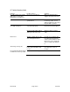
5) Trouble Shooting Guide Problem No audio and no In-Use LED light on the receiver when transmitter is on and In-Use Possible Causes Receiver is not powered Solutions Make sure that the power supply is properly connected Transmitter and receiver not synchronized No (or low) Audio with all InUse LEDs solid green Turn on transmitter and place in recharge cradle.
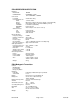
PR24 RECEIVER BASE STATION Indicators INUSE LED: CHARGE LED : Connections In Car Mic Un-terminated Cord RED BLUE BLACK YELLOW ORANGE GRAY Audio Connector Tip Ring Sleeve RF Specifications Frequency Range: Number of Channels: Diversity: Receiver Type: RF Sensitivity: FCC type acceptance: Audio Specifications Frequency Response: Audio Output Level: Distortion: Signal to Noise Ratio: Dynamic Range: General Specifications Range Power Supply: Current Draw: Size: Weight GREEN CHARGING -> RED FULL CHARGED -> GREE
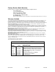
Factory Service (North America) If factory service is required, ship the unit prepaid in its original carton to: Telex Audio Service c/o Telex Communications 8601 East Cornhusker Highway Lincoln, NE 68507-9702 U.S.A. Tel: 402/467-5321 or 800-553-5992 Fax: 402/467-3279 Enclose a note describing the problem along with any other pertinent information and how to contact you.