Telex ® Operating Instructions RadioCom TM FM-1 QSB-1 SMP Professional Wireless Intercom System Management
Table of Content Section 1 Introduction . . . . . . . . . . . . . . . . . . . . . . . . . . . . . . . . . . . . . . . . . . . . . . . . . . . . . . . . . . . 1-1 Overall Description . . . . . . . . . . . . . . . . . . . . . . . . . . . . . . . . . . . . . . . . . . . . . . . . . . . . . . . . . . . . 1-1 Section 2 System Manager Program (SMP) Software. . . . . . . . . . . . . . . . . . . . . . . . . . . . . . . . . . 2-1 System Manager Program (SMP) . . . . . . . . . . . . . . . . . . . . . . . . . . . . .
-ii- Blank
Section 1 Introduction Overall Description The QSB-1 (Qard Serial Bus) pod interfaces with the SMP via a USB connection to the computer. This enables the user to download events into a small, convenient, DataFlash® card. FM-1 "Snap Shots" can also be uploaded to the SMP from the DataFlash® card via the QSB-1. The SMP Software along with the QSB-1 and FM-1 allow a user to easily manage large systems of BTR-1 base stations along with their beltpacks.
1-2 Blank
Section 2 System Manager Program (SMP) Software System Manager Program (SMP) Installing the Program (Step 1) 1. Insert the Manual/SMP Program compact disc into your CD-ROM drive. The program will automatically start. 2. Select the "System Manager Program" button. You will automatically go to the system manager page. C 3. Click on the "Install Software" button. The Setup Wizard screen will appear. Follow the Setup Wizard instructions on your screen.
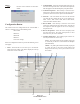
D C Launch ing the Sys tem Man ager Pro gram (Step 3) 1. Click on the computer desktop icon, shown to the right, to launch the program. 2. The following Screen will then appear: Figure 2-1 The main screen of the system manager program.
The main menu bar definitions are defined below: Using the System Manager Program The main screen displays the 10 base stations. FILE: 1. Event Name. New: Open: Save: 2. Base Name – A 10 character name for the base is displayed here. The name is entered in the configuration screens. Save as: 3. The Band Designation – Base 1, shown here, is a F1 base station. This indicates its transmit band is in the F band and it’s receive band is in the 1 band. See section 8 for band definitions.
2. Transmit Band – Select the transmit band of the base station from the drop down menu. This will set the frequencies that will appear in the transmit frequency drop down menu. HELP: About: Provides current software version information. 3. Transmit Frequencies – Enter directly or select the transmit frequency from the drop down menu. The range of frequencies to select from was set by the transmit band list. 4.
8. Sidetone - The sidetone is the amount of a user’s own voice that is feed back to their headphones. Both the beltpack and base stations sidetone my be adjusted. 4. IC in (Listen) – Sets the level of the intercom audio coming into the base station. Will be the only adjustment active if Listen Only is selected. 9. Transmit Power - The base transmit power can be set to the following positions: Normal = The transmit power is 10 dB below maximum power. This is 5 mW typically. 5.
Downloading / Uploading Af ter an event is set-up it may be down loaded to a DataFlash® card for the eventual downloading into a FM-1 and thus to a system of up to 10 base stations. A snap shot of a system of up to 10 base stations may also be uploaded to the SMP in order to examine the settings of the system for trouble-shooting, use the system as a ‘base line” for setting up other events, or just for records. Downloading an Event 1. Open FM-1 System Manger Program 2. Create an Event 3. Save Event 4.
Section 3 QSB-1 Connections QSB-1 The QSB-1 (Qard Serial Bus) pod interfaces with the SMP (System Manager Program) via a USB connection to the computer. The QSB-1 allows the user to download events into a small, convenient, DataFlash® memory card. Event(s) and Snapshot(s) of the system can also be uploaded to the SMP from the card via the QSB-1. NOTE: Item 2 is Located on back of Unit 2 The card for use with the QSB-1 is a 2 MB DataFlash® memory card.
3-2 Blank
Section 4 FM-1 Frequency Manager Front Panel Controls and Connections 1. Power Switch. Rear Panel Controls and Connections 2.
FM-1 Specifications Temperature Range..................................................................................................................-4°F to 130°F (-20°C to 55°C) Dimensions...................................................................................................................................19.0”W x 1.72”H x 8.02”D (48.3 cm x 4.4 cm x 20.4 cm) Weight..................................................................................................................................
Downloading a Card The following steps download a card to the FM-1. After programming the display will indicate the following: 1. From the event screen press
4-4 Blank
Section 5 FM-1 Menu Structure Figure 5-1 FM-1 Menu Flow Chart 5-1
5-2 Blank
Section 6 Software License End-User License Agreement for Telex® Software IMPORTANT - Please red this document carefully before using this product. THIS DOCUMENT STATES THE TERMS AND CONDITIONS UPON WHICH TELEX COMMUNICATIONS, INC. (the “COMPANY”) OFFERS TO LICENSE THE INSTALLED SOFTWARE OR PROGRAM (the “SOFTWARE”) FOR USE WITH THE PRODUCT IN WHICH IT WAS INSTALLED. YOU ARE AGREEING TO BECOME BOUND BY THE TERMS OF THIS AGREEMENT.
6-2 Blank
Section 7 DataFlash® Card Handling and Storage Precautions • Do not disassemble or remodel • Keep out of reach of children. Danger of swallowing.
7-2 Blank
Section 8 Frequency Bands Frequency Bands Band The BTR-1 system operates in TV channels 16 to 36 and 38 to 59. This is the frequency range of 482 to 608 MHz and 614 MHz to 746 MHz. The band, the TV channels and frequencies are shown in Table 2. Most bands are 18 MHz wide, however band 7 is 24 MHz wide. F H Bands F to E are always base transmit bands (beltpack receive bands). Bands 1-7 are always base receive bands (beltpack transmit bands).
8-2 Blank
Section 9 Replacement Parts and Accessories QSB-1 Card Reader P/N 879845 USB Cable P/N 600091 QSB-1 Kit Includes: QSB-1 Card Reader USB Cable DataFlash® Card Cat No.
9-2 Blank
TELEX COMMUNICATIONS, INC. • 12000 Portland Ave. South, Burnsville, MN 55337. PN 803996 REV B MARCH 2005 Made in U.S.A.