USER MANUAL I MODEL CM300 I Console Mount User Station I MODEL RM300 I Rack Mount User Station RTSTM 9350-2643-00Rev E 2/01
PROPRIETARY NOTICE CUSTOMER SUPPORT The RTS product information and design disclosed herein were originated by and are the property of Telex Technical questions should be directed to: Communications, Inc. Telex reserves all patent, proprietary design, manufacturing, reproduction, use and sales rights thereto, and to any d c l e disclosed therein. except to the extent rights are expressly granted to others. COPYRIGHT NOTICE Co yright 1994 by Telex Communications, Inc.. All rigKts reserved.
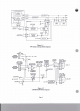
Figure 1-2 CM3001RMUW)Block Disgram
On the Model CM300/Rhi3w, a latching switch or 1.1 DESCRIPTION momentary push button tums the microphone on. The Model CM3W is a console mount, t w h l intercom user station. The Model RMUX) is a rack mnmt, two-chmd intmom user station. The user station is designed to he used in a full duplex, wafermce line intercom system. The mommtary push hutton allows quick bursts of Confereuce Line IntMcom Svstem (Figure 1-1) communication, especially useful in a high noise mvironmmt.
13 CM3oO/RM3Ml SPJXWICATIONS JI..hbwArdUir Input DC Voltage Voltage ruin ovlplt voltage 34dB 8 ~ ~puli-wprt l u into 25 n q t - lnwutpuliiatouobm FrrqmcyRapomt lSObemto8kiloktzr3dB NUI'EI DO NOT USE BEADPEONES THANISOHrds. SidUms - IMPEDANCESLESS -2OdBtoIullo. AdjmttncntRrqy (YCIIILL SpdiDgFrcqwyr ZO,WObem*1whcRE -u 5haas2bem B..*.tCrue(u MMiaophm XLRtypcCpi~tuM!C CuboDMicmpbmc llCIPsdudpboacj.cl53drevit u.rca8sdam InPt M XLRtypc3pinfcmk XLR typc ~ male ~ Ndrc..ML.r*.
NW: Opemdion of a aydm or maximum load dOCS not allow for other miations such as fempermun, line *e, able ,-er and s u w . A nwrt pnrdcni o p p m o a h & & o p c ~ ~ s y ~ ~ n o n o n f l r n n o8f 0 % 2.1 Power Rquhm&, Type Of System, PowMethod And Power Supply(i) -Pad*. Power Ranuremnts To maintain a bridging 10,000 ohm0 bpedanw to the intenmu line, the CM300/RM300 requires +18 to +35 volts DC.
23 millipmpms for tbe CM300/RM300, 33 millirmperes for tbe CM300URM300L). The ability of hadphones to shut out mwmted envi=ts Euviroampf Table 2-1 shows typical opentino o f o f mi= p d . and tbs A very quid openting mvhmnmt, such as a television studio, may require that Damd does not leak from the headphones, meanbig the badphoaes should have good 'acoustic isolation'.
Anotha bmsfit of not "earth" grounding the circuit return is tht it prevents the h t m h t i o n of noise through 'earth" curw(s from other equipmeat. If the RTS Systmes circuit gmund~tsthsc~l~nts,itisWrdythattheywillbc hevd is interfering noise on the d 4 o n line. Wirsri?rcddsrrninssthe~opwrtingdist.nCc (where the DC voltage drop is the limiting factor). Ths following eqlutioas apply for a wndnctor size of #22 AWG. a minimwnuser station voltage of 18.
IntheIWIn~systemd~sluroscommm ciraritgrcundrshnn. due to common^ XLR431 m k ~cmbeducedbyn6ing22pylcnhieldeduMe, I I I ~ ~ M : -55 m u , n~mirul and~elillgsbidddninwinswithcircuitrchunwirrs. Output Lvclto lll!d&onc: 10 volta pak-tc-pd. Capacitive cmssWL cm be raducsd by using rwo rbidded apm circuit. jmir. O w w i r s o f o n c ~ ~ t o c b r n n e l o n a ( p i n 2 ) , a ~ ~ 0 f b 0 o t b t r ~ ~ t o E h . n n a ~ @ i n 3 ) Pin1-M*ropbwcbw , the nmrining wires are circuit retmn (pin 1).
Table 2-1 Table 2-2 T y p i d Openting Envircammts, Embmmtal Noise,Sormd PIcssureLsvel, a t 1 0 ~ ~ T y p i d Opeding Environments, ~PrcssureLevel, at= sQw2 Seb, Aimaft 120dBto160dB Orchestra, 75 p i e , (Perlis) or Pipe org.n,(PerLs) Rock Concat 140 dB 11OdBto140dB Pirno,Parks 120 dB Blaring Rdio 110 dB Cmtrifugd Vmtilrting F m 110 dB Auto on Highway 100 dB m s@x!zi Muimum AUomb1.
Figure3 Fmnt Panel, Model CMU)O/RM300 User Station Page 12
SECTION 3: OPERATION 3.1 Operating Controls And Conaectors The r e f m c e numbcrs in below comspond to the circled numbers in Figure 3. Ref No. Name 1) CHannel & k t Switch 1 2 Selects 1of 2 cham& (staadard) or 1of 3 chPnncls ( o p t i d ) . The optional Call Light operates on the channel selected by this switch. Tbe CHmuel select switch is omitted in the Single Chnnrd (SC) option.
Sectim 7: DIAGRIMS I DRAWINGS Dacumcnt Nunbet m These dnnvingaapplies 0 CM300 Unifs with CC33 or CC40 wnlr. . . . . . . . . . . . . . . . . . . . . . . . . . . . . . . . -15 Installation hawing. CM300. . . . . . . . . . . . . . . . . . . . . . . . . . . . . . .16 OD2993 A Outline hawin& CMU)O. ID2993 A These dnawings applicp & CM300lRM300 Units with CC33 orCC40 d. - A Cable Wiring Diagrams,2Chwncl SystemM!ha~elSystem TM1786 B 12-volt Battcry Opedon/ Tckpmdoctim Systean Exampk . . . . . . . . .
0D2993, Outline Drawing, CM3OO Page 15
Page 16
Channel 2 3 n 3 Common I Channel 1 2 Common 2 I Drain Wins 1 To Supply N.C. ,L-1I, - 1 To Station --, n Gm 3 - Channel 3 Elk Red 3 , , N.C.
Page 18
Page 21
-ma -u (I, - .. <-a) DEmIII~nuUc-CIllm- 1 R?=- mraarrsra i m n - :- . : I -.