Alarm GPIO Expansion Module www.telexper.
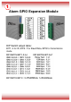
1 Alarm GPIO Expansion Module DIP Switch adjust table: BIT1~4 for ID, BIT5~7 for Baud Rate, BIT8 for transmission mode
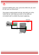
2 Connect nGPIO’s DT+ (D+) pin to the nVS’s D+ pin, and DT-(D-) pin to nVS’s D-pin. The power could provide from the 12V OUT pin of the Video Server, and make sure both of the GND pin connected well to enable the power supplying.
3 The steps listed below show you how to configure all the hardware and software: 1. Use the DIP Switch to change the ID / Baud Rate / Mode setting. 2. Please connect the devices as the example picture shows below: Alarm 1 NO 1 Controller Alarm Sensor NC 2 Alarm 2 NO 3 Alarm 3 NO4 Alarm 4 Control Out GND Alarm In GND CMS Setup For setup and operations on CMS, please refer to the complete User Manual.