
User's Guide

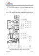

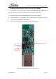


Table Of Contents

User Guide for Telink TLSR8266 Debugging Dongle
AN-16101600-E1 11 Ver 1.0.0
3.5 Test GPIOs for 8266 Dongle
Since all GPIOs of Telink TLSR8266 debugging dongle board are already
connected to corresponding pins of headers including J4, J18, J21 and J22, user can
directly test GPIO signals on header pins.
Note:
Only J4 and J20 are soldered on 8266 debugging dongle demo board supplied by
Telink. User needs to solder J18, J21 and J22 for development purpose.
Figure 7 Test GPIO signals on header pins
J4
SWS
GND
3V3
J18
PE4
PF0
J22
J21
PC7
PC4
PC1
3
PA1
PC2
1
PC6
PE6
PE5
PE7
PA5
PF1
PB0
PD4
PC0
GND
3
PD5
3
J20