
User's Manual

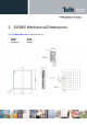

GE865 Hardware User Guide
1vv0300799 Rev.6 - 04/06/09
Reproduction forbidden without Telit Communications S.p.A. written authorization - All Rights Reserved page 7 of 58
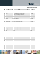
3 GE865 module connections
3.1 PIN-OUT
Ball Signal I/O Function Note Type
Audio
E8
EAR- AO Earphone signal output, phase - Audio
D8
EAR+ AO Earphone signal output, phase + Audio
B8
MIC+ AI Mic.signal input; phase+ Audio
C8
MIC- AI Mic.signal input; phase- Audio
SIM card interface
A5
SIMCLK O External SIM signal – Clock 1,8 / 3V
A8
SIMRST O External SIM signal – Reset 1,8 / 3V
A6
SIMIO I/O External SIM signal – Data I/O 4.7K Pull up 1,8 / 3V
B7
SIMIN I External SIM signal – Presence (active low) 1,8 / 3V
A7
SIMVCC - External SIM signal – Power supply for the SIM 1,8 / 3V
Trace
D1
TXD_AUX O Auxiliary UART (TX Data) CMOS 2.8V
E1
RXD_AUX I Auxiliary UART (RX Data) CMOS 2.8V
Prog. / Data + HW Flow Control
A3
C103/TXD I Serial data input (TXD) from DTE CMOS 2.8V
A4
C104/RXD O Serial data output to DTE CMOS 2.8V
B3
C108/DTR I
Input for Data terminal ready signal (DTR) from
DTE
CMOS 2.8V
A1
C105/RTS I
Input for Request to send signal (RTS) from
DTE
CMOS 2.8V
A2
C106/CTS O Output for Clear to send signal (CTS) to DTE CMOS 2.8V
B5
C109/DCD O
Output for Data carrier detect signal (DCD) to
DTE
CMOS 2.8V
B2
C107/DSR O Output for Data set ready signal (DSR) to DTE CMOS 2.8V
B4
C125/RING O Output for Ring indicator signal (RI) to DTE CMOS 2.8V
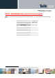
DAC and ADC
G7
DAC_OUT AO Digital/Analog converter output D/A
F5
ADC_IN1 AI Analog/Digital converter input A/D
F6
ADC_IN2 AI Analog/Digital converter input A/D
Miscellaneous Functions
C1
RESET* I Reset input
H2
VRTC AO VRTC Backup capacitor Power
G8
STAT_LED O Status indicator led CMOS 1.8V
B1
ON_OFF* I
Input command for switching power ON or OFF
(toggle command).
47K Pull Up Pull up to VRTC