
User's Manual

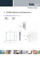

GE865 Hardware User Guide
1vv0300799 Rev.6 - 04/06/09
Reproduction forbidden without Telit Communications S.p.A. written authorization - All Rights Reserved page 8 of 58
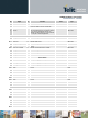
Ball Signal I/O Function Note Type
E2
PWRMON O Power ON Monitor CMOS 2.8V
H5
Antenna O Antenna output – 50 ohm RF
H1
Service I
Service pin shall be used to upgrade the
module from ASC1 (RXD AUX, TXD_AUX).
The pin shall be tied low to enable the feature
only in case of a Reflashing activity. It is
required, for debug purpose, to be connected
to a test pad on the final application.
CMOS 2.8V
GPIO
D3
GPIO_01 I/O GPIO01 Configurable GPIO CMOS 2.8V
D2
GPIO_02 / JDR I/O GPIO02 I/O pin / Jammer Detect Report CMOS 2.8V
E4
GPIO_03 I/O GPIO03 GPIO I/O pin CMOS 2.8V
H7
GPIO_04 / TX_DISAB I/O GPIO04 Configurable GPIO / TX Disable input CMOS 2.8V
G2
GPIO_05 / RFTXMON I/O
GPIO05 Configurable GPIO / Transmitter ON
monitor
CMOS 2.8V
H8
GPIO_06 / ALARM I/O GPIO06 Configurable GPIO / ALARM CMOS 2.8V
G6
GPIO_07 / BUZZER I/O GPIO07 Configurable GPIO / Buzzer CMOS 2.8V
D4
GPIO_08 I/O GPIO08 Configurable GPIO CMOS 2.8V
F4
GPIO_09 I/O GPIO09 4.7 K Pull Up Open Drain
E3
GPIO_10 I/O GPIO10 4.7 K Pull Up Open Drain
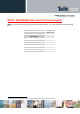
Power Supply
F1
VBATT - Main power supply (Baseband) Power
F2
VBATT_PA - Main power supply (Radio PA) Power
F3
VBATT_PA - Main power supply (Radio PA) Power
G1
GND - Ground Power
C2
GND - Ground Power
C7
GND - Ground Power
E5
GND - Ground Power
E7
GND - Ground Power
G5
GND - Ground Power
G4
GND - Ground Power
G3
GND - Ground Power
H3
GND - Ground Power
H6
GND - Ground Power
RESERVED
B6
-
C3
-
C4
-
C5
-
C6
-
D5
-
D6
-
D7
-
E6
-
F7
-
F8
-