
User's Guide


LE910Cx HW User Guide
Doc#: 1VV0301298
Rev. 2.0 Page 38 of 120 2018-11-19
Logic Level Specifications
Unless otherwise specified, all the interface circuits of the LE910Cx are 1.8V CMOS logic.
Only few specific interfaces (such as MAC, USIM and SD Card) are capable of dual
voltage I/O.
The following tables show the logic level specifications used in the LE910Cx interface
circuits. The data specified in the tables below is valid throughout all drive strengths and
the entire temperature ranges.
NOTE:
Do not connect LE910Cx digital logic signals directly to OEM digital logic
signals with a level higher than 2.7V for 1.8V CMOS signals.
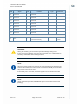
4.3.1. 1.8V Pads - Absolute Maximum Ratings
Table 10: Absolute Maximum Ratings - Not Functional
Parameter Min Max
Input level on any digital
pin when on
-0.3V +2.16V
Input voltage on analog
pins when on
-0.3V +2.16 V
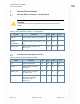
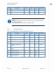
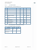
4.3.2. 1.8V Standard GPIOs
Table 11: Operating Range – Interface Levels (1.8V CMOS)
Pad Parameter Min Max Unit Comment
V
IH
Input high level 1.25V -- [V]
V
IL
Input low level -- 0.6V [V]
V
OH
Output high level 1.4V -- [V]
V
OL
Output low level -- 0.45V [V]
I
IL
Low-level input leakage
current
-1 -- [uA] No pull-up
I
IH
High-level input leakage
current
-- +1 [uA] No pull-down
R
PU
Pull-up resistance 30 390 [kΩ]