
User's Manual
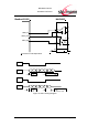
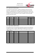
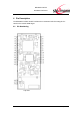
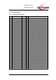

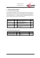

Table Of Contents
- Introduction
- Block Diagram
- Application Interface
- Pin Description
- Electrical Characteristics
- Mechanical Characteristics
- Approvals/Certifications
- Related Documents
- Ordering Information
- History

BlueMod+C11/G2
Hardware Reference
www.stollmann.de Page 14 of 42
3.6.4 Analog to Digital Converter
Three ADC channels with 8 to 10bit resolution in reference to 1.8V are available. A
wide range of trigger sources and programmable S&H timing are available.
Pin #
GPIO#
IO Name
Alternative
Signal Name
Description
Direction
A16
JTAG-RES#
AD3
ADC channel
3
In
analogue
A12
GPIO10
AD0
ADC channel
0
In
analogue
A11
GPIO8
AD1
ADC channel
1
In analo-
gue
3.7 Bluetooth radio Interface
The BlueMod+C11/G2 offers three population variants for the antenna
1) The BlueMod+C11/G2/AE variant presents a 50Ω impedance antenna interface
on a Radiall UMP connector, type R107103020. See http://www.radiall.com/
2) The BlueMod+C11/G2/AI variant presents an integrated ceramic antenna.
In both cases the Pins A-26 – A-28 can be left unconnected.
3) The BlueMod+C11/G2/AP variant presents a 50Ω impedance antenna interface
on pin A-27 with adjacent GND pins A-26 and A-28. In this case Pin A-26 and A28
shall be connected directly to the reference GND plane. Signal routing of the RF
signal on customer PCB has to be implemented with 50R micro-strip line technique.
If the antenna performance does not meet your requirements or you need antenna
support, please contact Stollmann.
3.8 JTAG
For software development purposes a full JTAG interface, connected to the ATMEL
MCU is available.